The original version of this article appeared in The MedFER News during the brief history of that fine publication. I've revised the article and submitted it to the LOWDOWN because the technique described is equally useful for LowFER and MedFER transmitters.
Tuning a LowFER or MedFER transmitter and antenna for maximum output is usually a kind of juggling act. One eye has to watch the RF output while the other eye checks the final amplifier current to keep the DC input power at or below the FCC limit. Here is a simple way to guarantee that the input power to your final won't exceed the limit no matter how you tune the antenna. With this technique you can concentrate on getting the maximum RF output from your transmitter and let the limiter take care of the input power. You will also find that your input power remains above 90 per cent of the limit even if the final amplifier DC current varies by plus or minus 30 per cent because of wet insulators, ice loading or whatever. A side benefit is that the current can't rise to extremely high values and turn the transistor(s) into instant toast, which may otherwise happen with some final amplifiers if they are tuned off resonance.
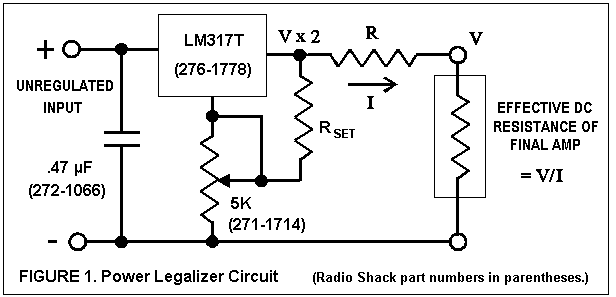
All it takes to do this is a regulated DC voltage source and a resistor. Figure 1 shows one way of implementing the technique if you don't already have a regulated power supply with the right output voltage. If the final implifier works best at a voltage V, you use a variable supply or IC voltage regulator that puts out a voltage equal to two times V. A series resistor R is inserted between the regulated output and the load.
It's easy to prove mathematically that maximum power is delivered to the load when the effective load resistance presented by the amplifier (the voltage across the final amplifier divided by the current) is equal to R. The way the arithmetic works out, the value of R needed to limit the transmitter power to 1 watt is simply V2, and for 100 milliwatts R must be equal to 10 times V2. Suppose you want to deliver a maximum of 1 watt with 13 volts applied to the final. Then the supply voltage will have to be 26 volts and the series resistance must be 169 ohms. For a 100-milliwatt transmitter that likes to operate at 5 volts, the supply voltage should be 10 volts and the required series resistance is 250 ohms. (These are the values I'm presently using on LEK and MIN, respectively.)
The LM317T adjustable regulator circuit in Figure 1 provides a voltage range of about 1.2 to 17 volts with RSET = 390 ohms, and 1.2 to 28 volts with RSET = 220 ohms. You can also use a fixed regulator such as the 7800 series. Typical solid-state regulators have a "dropout" (input- output differential) of about two volts, so the unregulated input voltage should be at least two volts above the highest regulated output voltage. An input bypass capacitor (.47 microfarad or greater, preferably tantalum) is required to keep the regulator from going into self-oscillation and should be placed close to the regulator terminals. It isn't shown on the diagram, but it is assumed that there is an adequate RF bypass capacitor internal to the final amplifier. Make sure the capacitor is rated for a voltage higher than the supply voltage. A Zener diode can also be added across the final to keep the voltage below the safe rating of the transistors.
If you short-circuit the final amplifier, the power dissipated in the series resistor will be 4 times the power used by the amplifier in normal operation. A 1/2-watt resistor is OK for a MedFER transmitter but a 4-watt resistor is needed to handle all load conditions in a LowFER application. To get the value of resistance you need and to meet the power rating requirements, you can use combinations of 1/2-watt, 5 per cent resistors listed in the Radio Shack catalog. For example, a 169-ohm, 4.5 watt resistor can be made from nine 1/2-watt, 1500-ohm resistors in parallel. The actual resistance in this case would be 166.67 ohms, if all the resistors were precisely 1500 ohms to start with. I suggest that you try to get within a few percent of the desired value of R and measure the actual value with a digital multimeter. Then you set the supply voltage to 2 times the square root of R to limit the transmitter power to exactly 1 watt, or 2 times the square root of R/10 for a 100-milliwatt limit.
You don't have to know the exact optimum voltage in advance. In fact, the limiter circuit is a very effective aid in determining the best operating point for your transmitter. You can design the limiter circuit based on an educated guess, measure the voltage the final has "chosen" after the antenna current or field strength is maximized, and use this value to determine new values for the supply voltage and series resistance. One or two iterations will get you as close as you ever need to be if your first guess was anywhere near the target.
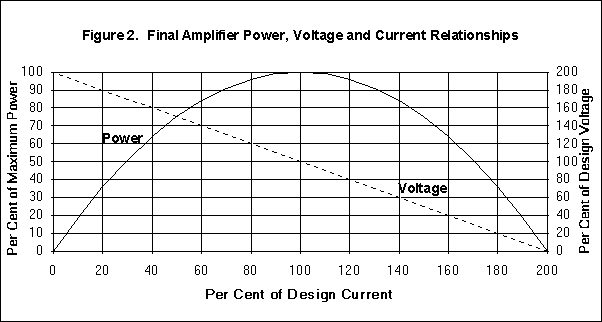
Figure 2 shows the relationships between input power, voltage and current in a final amplifier using the limiter circuit. Maximum power occurs when the final voltage and current are at their design values. Even if the final current or voltage is off by 30 per cent, the power input to the final remains above 90 per cent, less than 0.5 dB down from the maximum. To put this in perspective, a signal strength change of 0.5 dB is undetectable by the human ear, and will move the S meter on a typical receiver by about the width of the needle.
Lyle Koehler
This article from The LOWDOWN is protected under US and international copyright laws. Please obtain the author's permission before redistributing this document or reproducing it in any other form.
potrzebie