|
Measuring the earth resistance of an LF-antenna system By Dick Rollema, PAØSE
There were some requests for info on the way I measured the earth resistance of my antenna system. In 1988 I made an impedance bridge with a noise source. (See the circuit diagram below.) Most bridges of this type have a transformer between the noise amplifier and the bridge circuit. But I found it impossible to make the bridge frequency independent up to 30MHz. By putting the transformer between the bridge circuit and the detector I managed to make the readings reliable up to 30MHz. When the bridge is used at LF only the matter of frequency compensation does not arise. For measuring earth resistance I connect the bridge between the bottom end of the loading coil and the earth connection, after disconnecting the transmitter from the coil. The X-control is left at the zero (centre) position. (C2 is then equal to C1). The detector is tuned to the frequency f0 where the earth resistance is to be measured and the vacuum capacitor in parallel with the loading coil (or the coil itself) and R3 of the bridge varied for minimum noise. The minimum is so frequency-dependent that it becomes deeper as the bandwidth of the receiver is reduced! The total resistance of the antenna system can then be read from the R-control R3. But for better accuracy I measure the value of R3 using a digital multimeter. From the value so found I subtract the loss resistance of the loading coil. What remains I call the earth resistance. Of course in that value are also included the radiation resistance and the resistance of the aerial and earth wire, But these quantities are negligible as compared to the earth resistance. In the earth resistance will also be included losses in the antenna insulation and in the capacitance of the antenna to surrounding objects like trees (no trees in my case). But these losses are impossible to separate from the real earth resistance. Measuring earth resistance at 50Hz has no meaning for the loss at LF because the earth resistance (impedance is more correct) is frequency dependent. At low frequencies the earth acts like a resistor, at high frequencies like a capacitor in parallel with a resistor. I find the loss resistance of the loading coil as follows. I use my W & G signal generator and tracking selective voltmeter type PSM-5. The generator is connected to a one-turn loop that is positioned at some 35cm from the bottom end of the coil. An oscilloscope probe is connected to the level meter and hung near the top end of the coil. The antenna is replaced by a variable capacitor (broadcast receiver type). The PSM-5 is adjusted to f0 and the variable capacitor tuned for maximum voltage over the coil and its value noted. The PSM-5 is then tuned to the higher frequency f1 and lower frequency f2 where the voltage over the coil has dropped to 0.707 (-3dB) of the maximum. The frequency difference f1 - f2 = B (I use a frequency counter to improve accuracy; B is rather small). This yields Q = f0/B . The value C of the variable capacitor is then measured. This yields the reactance of the capacitor X = 1/6.28 * f * C ohm. Because there was resonance this is also the reactance of the loading coil in parallel with its tuning capacitor. We now find for the loss resistance of the loading coil: R = X/Q. My measurements support the findings by Alan Melia. The earth resistance is higher in winter than in summer and is maximum when the earth is soaked with water. When the water freezes the resistance goes down. I hope this info is of some use. |
Click diagram to view full-size: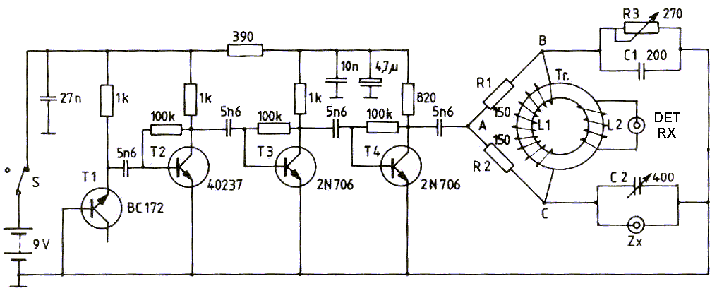
Click link here for a photo of Dick's noise bridge.