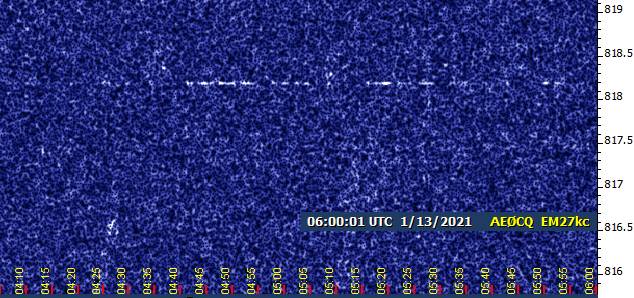
2200m VK overnight
I left the rx on 2200m to decode FST4W-1800 overnight. Propagation to VK appeared at 1030-1230z Jan 1, 2021 into Texas.
drive.google.com/file/d/1lO7DRmVRgosZDYXAQbGhk1FpmStcyc1z/view?usp=sharing
Unfortunately, these spots never made it to wsprnet. This time the problem was loss of pc wifi communication to router, and not wsprnet itself (which is the usual situation).
Reminder: Lowfer net +/- 3927Khz Saturday morning 0800 California time
Posted by Jerry Parker on January 01, 2021 at 15:54:58.
Reminder: Lowfer net +/- 3927Khz Saturday morning 0800 California time
Or listen online at kfs:
http://69.27.184.62:8901/?tune=3927lsb
or
KPH Point Reyes:
http://198.40.45.23:8073/
or
Utah Web sdr:
http://www.sdrutah.org/websdr1.html
If you cannot get into the net on 80 meters you can listen on KFS and participate by sending net control your thoughts to wa6owr@gmail.com
73
Jerry WA6OWR
Re: 2200m WSPR2 vs FST4W-120 test
Posted by Garry, K3SIW on January 01, 2021 at 17:02:52.
In reply to 2200m WSPR2 vs FST4W-120 test posted by Paul N1BUG on December 31, 2020
Paul et al,
I ran jtdx2.2.0-rc152 to decode wspr-2 over night, along with wsjtx2.3.0-rc2 to decode fst4w-120. Based on 108 decodes within 2 minutes of each other, the average SNR advantage for fst42-120 over wspr-2 was 0.66 dB, with a std dev of 2.38 dB and std dev of mean of 0.23 dB. The median difference was 1 dB with a quartile spread of 2 dB. I think the jtdx code is a bit more sensitive than wspr codes at the expense of higher falsing probability.
I'll send a spreadsheet of the results to Paul via email.
73, Garry, K3SIW, EN52ta, Elgin, IL
Re: 2200m WSPR2 vs FST4W-120 test
Posted by Paul N1BUG on January 01, 2021 at 20:31:28.
In reply to 2200m WSPR2 vs FST4W-120 test posted by Paul N1BUG on December 31, 2020
I will be running this test again tonight. Winter storm tomorrow so not sure about future nights.
Paul
2200m rx Japan into CONUS
Posted by swlem3 on January 04, 2021 at 15:30:02.
Propagation was favorable overnight to decode Japan into the CONUS on 2200m using FST4W-1800 mode. K9AN and swlem3 decoded stations JA1NQI and JA1RWI.
drive.google.com/file/d/1bCTP_0BHYVjK9EHcNLQtheGzioEb343U/view?usp=sharing
Working conditions for reception at swlem3: Asus tablet w/ Elad S2 sdr fed by a miniwhip active antenna up 15 ft.
Ray ... N. Central Texas
New Year HiFERs
Posted by Ed Holland on January 04, 2021 at 19:31:44.
Happy New Year to all!
The long weekend provided opportunities for monitoring 22m, (and also a little time on 630 m).
Conditions were interesting for the main part, especially New Year's Eve and New Year's day. EH made its common place appearance, often quite prominently, along with NC. What is most likely ROM is also a frequent visitor - definite trace but often hard to read for a clear ID. At several times, there were between four and five traces visible at the "Watering Hole". 7P was less reliable, but made a spectacular fade-in during in-person monitoring on NYD mid-morning, loud and clear over the Icom's speaker.
I'll go through the charts later and add some screenshots.
630m Provided some fair WSPR decodes last night (3rd/4th Jan) but nothing out of the ordinary, and many repeats of "neighbors" here in CA. I wonder if activity in this mode is reduced by comparison to last winter?
73s to all,
Ed
Report on Board Software Test
Posted by John Davis on January 04, 2021 at 20:18:51.
The 30 December test was prompted by a recent rash of duplicate posts. One was an attempt to "bump" an earlier message, but the rest seem to have been driven by users not seeing that their first attempt was successful.
(This is a long post, but I hope you'll read it through and share any of your own observations that may help.)
Now, as I have written before, if you get the Confirmation Page, your message was posted and is listed for others to see! This is the closest thing to a TOTALLY FAILSAFE mechanism as it is possible to have anywhere on the Internet, because it doesn't just rely on my own Perl code; it is based on core functions of the Web host itself, and an Apache server running on Linux is probably the most widely tested software in the world today.
When you post a message to the Board, here is the (simplified) sequence of events which takes place. Your computer--or your proxy, if using a VPN--connects to our server, and passes along certain required variables along with your data from the posting form. The server calls the board software, which proceeds to do the following, in this order:
1. Gets the system time and prepares a timestamp to use if the message proves legit.
2. Retrieves the ENV variables from the HTTP request sent to the server and checks to make sure the required fields are present and are internally consistent. Since most automated message board spammers tinker with this data, having this test early saves a lot of processor time in rejecting spam. This code is not entirely perfect, but it is pretty effective, if I may say so. Out of 200 to 300+ attempts to spam the board daily, most are trapped right here.
3. Extracts data from the posting form and assigns it to variables for further processing.
4. Tests the form variables. This involves several subroutines that include tests for Authenticated Author passwords, stripping HTML from posts that aren't authenticated, and testing for spam keywords. (The latter also is not perfect, but reasonably effective.)
5. If the message has reached this stage successfully, the new file number is assigned and the message is assembled into final form. The next three steps are DO-OR-DIE. In them, a file is opened, written, and closed under direct supervision of the operating system. If Linux reports any failure in the file operations, the program drops dead on the spot. Do, or do not; there is no 'try.' Period. End of story.
(a) The New Message file itself is created. Do-or-die!
(b) Add a link to the message in the Threaded Messages file. Do-or-die!
(c) Add links in the appropriate Chronological Messages files. Do-or-die!
6. If the message is a followup to one or more earlier posts, the threading information is added to all such posts.
7. Now, and only now, is the Confirmation Page written by the software and returned to the user.
8. Diagnostic log files are written and the program ends.
Did you follow that flow? It's theoretically possible for things to go wrong at any one step, but... believe whatever wacko conspiracy theory you like... it is still physically impossible to receive the Confirmation Page unless 5(a) and 5(b) and 5(c) all happen successfully first!
Hence, as I always say: If you get confirmation, the message 100% absolutely is on the Board.
So, why does it sometimes refuse to show up for a while? That's usually the browser's fault, for reasons I go into a bit in the Message Board FAQ.
Wednesday's test was to see if anything I could do at the server side would improve newer browsers' ability to recognize when the list is updated. The code to "touch" the timestamp of the static part of the Message Board index page does work reliably on the server--but doesn't appear to help browsers as much as I hoped it would.
I tested Internet Explorer 11 (my baseline minimum for testing our pages these days) and Firefox in Windows 7 on a Dell desktop and an Acer notebook, and Firefox and Edge on a Windows 10 HP notebook. A friend at another location used Safari and Chrome on different computers. This ended up taking over three hours instead of the two I'd estimated, partly because of the number of browsers tested and partly because of some unexpected behaviors that required further investigation.
Firefox presented the biggest surprise. It refreshed pages successfully while our server was running the new software, so I thought "great!" ...except it also did fine with the older Board software that night! I'd previously documented instances where I could not force it to reload a page with F5, its little clockwise-circle reload button, or Ctrl+R, and it wouldn't display new content until I shut down all open Firefox windows and restarted it. But it absolutely refused to misbehave last Wednesday night!
That leaves me with two vague possibilities re: Firefox. Either the update Mozilla pushed on me shortly before the test fixed some unknown problem, or the fact that I had restarted Windows itself earlier that day had cleared up some cache issues.
Edge on the HP presented another surprise. F5 didn't work at all, not on pages created with the old software nor on ones touched by the new code. I discovered that, although HP had not assigned the F5 key to any hardware control functions, it was still necessary to press Fn with F5 to induce Refresh to a Web page or update a Windows Explorer list. I suppose that could be reassigned in 10's version of Control Panel, but who wants to bother with that?
As for the other browser/hardware combinations, not all of those got definitive comparisons under both old and new Board software. However, none required going all the way to Ctrl+F5 to force a complete Refresh with the new software, so I'm going to assume partial success until contradictory information turns up.
With that in mind, I've revised the FAQ advice for updating message lists after posting, if F5 isn't enough to show the new post: try Ctrl+F5, or Fn+F5 on smaller devices, and/or close all open instances of the browser before restarting in severe cases.
Your observations and feedback will be most appreciated. Re: 2200m rx Japan into CONUS
Posted by Garry, K3SIW on January 04, 2021 at 23:12:53.
In reply to 2200m rx Japan into CONUS posted by swlem3 on January 04, 2021
Very impressive DX Ray. Since K9AN also decoded Japan I might have too but instead spent the night listening to FT8 on 160 mtrs. Turns out last night didn't produce any JA decodes there but the night before yielded dozens, along with almost 40 countries decoded using an eprobe in 12 hours.
73, Garry, K3SIW, EN52ta, Elgin, IL
Re: 2200m rx Japan into CONUS
Posted by swlem3 on January 05, 2021 at 01:51:58.
In reply to Re: 2200m rx Japan into CONUS posted by Garry, K3SIW on January 04, 2021
Thanks Garry, for once I was in the right place at the right time. Your right, that since K9AN copied, I'm sure you would have also. Unfortunately, most of us can't set up rx everywhere, so decisions have to be made. Sometime we guess right and catch the dx, many times not.
160m FT8 is a lot of fun. I can understand you hanging out there. That's a good band to go to when it's just too noisy on <500khz. Nearly 40 countries in 12 hrs on an e-probe. ... wow.
cul es 73 Garry,
Ray
lowFER Reception reports for 1-4-21
Posted by Andy, KU4XR on January 07, 2021 at 02:06:19.
Hi all:Links below are for lowFER receptions overnight ending 1-4-21.
EAR link:
https://www.dropbox.com/s/5igenv2fw3wfrde/EAR_1-4-21.bmp?dl=0
JH link:
https://www.dropbox.com/s/eho50kj9w8venok/JH_1-4-21.bmp?dl=0
TAG link, most decodes of TAG in a single night to this date:
https://www.dropbox.com/s/uihmr5v0t4po5lc/TAG_WOLF10_1-4-2021.bmp?dl=0
73, and Best DX to all: 137.777 kHz
Andy, KU4XR, Friendsville, TN. EM75xr
Posted by Joe vo1na on January 10, 2021 at 02:50:54.
Running a qrss 30 beacon 24/7 30 watts to a 20x100 m RL. ARGO in Windows 10 Home
Reports welcomed. Tnx & 73.
Joe
Posted by Frank Lotito on January 10, 2021 at 13:23:37.
I need help installing ARGO on a computer running Windows 10 Home, 64 bit. I have had ARGO running (and still running) on two old XP computers without issue. As my newer computers updated from Windows 7-to Windows 8-to Windows 10 I lost the ability to run ARGO on my newer computers. Any suggestions? I would rather not setup a Windows 10 computer for dual booting the operating system on start-up. I find DL4YHF's "Spectrum Lab" to intense for my plaque scared 78 year old brain, HI. Thank you 73 -
Re: 137.777 kHz
Posted by Garry, K3SIW on January 10, 2021 at 13:31:13.
In reply to 137.777 kHz posted by Joe vo1na on January 10, 2021
LF conditions here were not as good last night as they have generally been lately. Nonetheless, the VO1NA beacon on 137.777 kHz came through weakly via QRSS30 during a brief look at the frequency. Moved then to 181.818 kHz and also found lowfer JH in there, again weakly, using ARGO at QRSS60. Screen captures at http://mailman.qth.net/,
73, Garry, K3SIW, EN52ta, Elgin, IL
Re: ARGO in Windows 10 Home
Posted by swlem3 on January 10, 2021 at 16:02:34.
In reply to ARGO in Windows 10 Home posted by Frank Lotito on January 10, 2021
Frank, I know this isn't exactly your situation but I'm running Argo on an Asus tablet ... Windows 10 Home 32 bit. The tablet has a 64 bit processor. I'm sure someone will stop by on this forum and give you some help. I'm not "up" to messing with spectrum lab either. :-) just fyi...
Ray
Re: ARGO in Windows 10 Home
Posted by swlem3 on January 10, 2021 at 16:14:13.
In reply to ARGO in Windows 10 Home posted by Frank Lotito on January 10, 2021
Frank, forgot to mention that if you have it installed and it won't run, right click on the Argo icon. A menu will come up, then click on Properties. You will see a tab that says "Compatability". There are settings there you can check out.
Ray
Re: 137.777 kHz
Posted by swlem3 on January 10, 2021 at 16:24:52.
In reply to 137.777 kHz posted by Joe vo1na on January 10, 2021
Hi Joe, I'm curious to know the "orientation" of the loop. Where are the nulls? I'd like to make sure that my location wouldn't be in a null before giving it a try. I'm in N Central Texas.
Ray
Sunday Noon HiFERs
Posted by John Davis on January 10, 2021 at 21:54:29.
Nice to see JB back on my first DXpedition in 12 days. Also ABBY, ODX, WAS, and KAH audible (at 13566.565, .465, .230 and .005, respectively); K6FRC visible only; TON intermittently visible; PLM QRSS nicely visible most of the time, sometimes audible; and WV fair.
At the watering hole, NC was up around 13,555.550; 7P, EH, RY and ROM all around their usual spots, and JB down at .280.
Re: ARGO in Windows 10 Home
Posted by John Davis on January 10, 2021 at 22:15:25.
In reply to ARGO in Windows 10 Home posted by Frank Lotito on January 10, 2021
Hi Frank. Are you trying to run an older version of Argo? Not all of those may be happy with updating your version of Windows; that is, even if they ran on the same machines under Windows 7, the upgrades to 8 and 10 may have "broken" the previous Argo installation.
You might do OK with what Ray mentioned about Compatibility settings, but if not, my suggestion would be to uninstall the previous version of Argo and download a fresh copy of Build 145 from www.weaksignals.com to install. I've just done a clean installation of that version to my new Windows 10 machine, and it was smooth as the proverbial silk.
Good luck, and let us know how it goes for you.
Lowfer KE
Posted by John Hamer on January 11, 2021 at 14:23:50.
KE has made some more improvements and seems to be coming in even stronger. I have been running a live grabber at the link below:
http://jwhamer.me/grabber/
John Hamer
VLF success!
Posted by John Bruce McCreath on January 11, 2021 at 14:59:03.
A quest that I set out on back in mid-October culminated in success last evening when I received the French VLF station HWU on 18.3 and 20.9 kHz. Antenna was an AMRAD active whip, with a VE3EAR modified PA0RDT Bias-T, feeding a G3XBM grounded gate preamp impedance matched to a Win7 PC sound card running Spectrum Lab's VLF SDR.
73, J.B., VE3EAR Re: VLF success!
Posted by John Hamer on January 11, 2021 at 16:35:16.
In reply to VLF success! posted by John Bruce McCreath on January 11, 2021
John,
Just curious, what is the impedance of your sound card? I have been thinking about making a VLF antenna setup lately.
Regards, Re: Sunday (Late After)noon HiFERs
John Hamer
Posted by John Davis on January 11, 2021 at 20:10:54.
In reply to Sunday Noon HiFERs posted by John Davis on January 10, 2021
Late in the noon hour CST, even PVC made a few partial appearances for just a few minutes 13555.503 kHz (a V here, part of a P there, part of a C another time). Shortly thereafter ROM started looking feeble. Between 1855 and 1857 UTC, right when JB was at its strongest for the afternoon, ROM went away entirely. An hour and one minute later, it reappeared faintly, then at 2002 it abruptly returned to normal level.
7P, EH, RY, ROM and JB continued together relatively stable at the watering hole until 3:00 PM CST (2100), by which time copy of JB was more intermittent. At 2134, ROM took another big dip in level, then vanished for the final time at 2137. JB endured 15 more minutes, then went away too.
EH and RY continued on solid, with 7P now a bit variable. Codar started in at 2215. At 2217, MTI abruptly appeared at audible level, and remained visible most minutes thereafter, if not always audible. Intermittent OTH radar pulses cranked up too. Then, RY faded into oblivion at 2221, with EH doing likewise two minutes later, leaving 7P and MTI alone at the watering hole.
Around 4:40 PM CST I decided to wrap up the afternoon with a quick band scan before switching to the 1750 m watering hole for the night. There was no longer any sign of WV or PLM. After sitting on TON's frequency for two minutes, I was about to declare the same for it. However, it suddenly became visible and then faintly audible...for 30 to 40 seconds, then went away again.
VAN was immediately visible at 2243 when I tuned to 13563.170, with keying just faintly detectable by ear at first. Subsequent ID cycles showed only the hooked dash-after-3-IDs.
K6FRC varied from no visual trace for 20 to 30 seconds at a time, to good solid audible copy for four to six IDs.
At 2252 UTC I transitioned to 1750 meters.
Re: Sunday (Late After)noon HiFERs
Posted by Ed Holland on January 11, 2021 at 21:34:37.
In reply to Re: Sunday (Late After)noon HiFERs posted by John Davis on January 11, 2021
Thanks for the report on PVC, John
You were lucky to catch PVC, your reception must have been only a short while ahead of it being taken off air for some monitoring. I will check my time records from the screen captures and report back on when PVC was operational.
Yesterday did offer some fair reception conditions. Alas, despite seeing the signal, I have yet to decode ROM's WSPR, and may well have just missed the best opening, seen on Spectrum Lab soon after starting receive operations, but before WSJT-x could be started up. Of course, ROM then retreated to much feinter levels.
EH, NC, Possibly JB or WM lower in range at the Watering Hole. Also, for a while, there was an unfamiliar (new?) signal, rendered as a CW dash in the QRSS3 display setting, placed around 13555.3xx kHz - will have to go back and check my captures for precise frequency details.
Here in CA, the band closed down mid-late afternoon, and PVC was returned to the air, ready for a normal work week.
Regards,
Ed
2200 m activity
Posted by Rick KA2PBO on January 11, 2021 at 22:39:49.
Im trying to capture VO1NA with no luck yet. Is there a list somewhere of other stations on 2200 m ? I want to see if its conditions or my set up .
Thanks
Rick
Re: Sunday Noon HiFERs
Posted by John K5MO on January 12, 2021 at 01:04:02.
In reply to Sunday Noon HiFERs posted by John Davis on January 10, 2021
Thanks for the logs, John. I'm glad to see that moving it didn't remove it from the spectrum entirely!
Re: ARGO in Windows 10 Home
Posted by Robert Mazur on January 12, 2021 at 05:21:20.
In reply to ARGO in Windows 10 Home posted by Frank Lotito on January 10, 2021
Stephen, W8LMF, wrote an excellent description of the program when installing older XP programs on later Windoze OSes. http://www.wa8lmf.net/aprs/UIview_Notes.htm
He did this because of the program with UVIEW ARPS uses who had problems with W7 and up.
Basically install in C:\Argo or say C:\Ham Radio\Argo. Anywhere but the installation program's default C:\Program Files\.
Even with newer programs, I always override the default installation directory if it points to C:\Program Files\ and install it anywhere else!
LF Sunday Night
Posted by John Davis on January 12, 2021 at 07:03:48.
Static was relatively low Sunday evening, so I thought I'd try the 1750 meter watering hole for the first part of the evening. After establishing baseline levels for signal there for a few hours, I would then make a quick check for EAR, and if that looked promising I'd move on down to 2200 m and try for VO1NA.
Well, despite modest noise levels, propagation wasn't very favorable for anyone but WM...and even Mike's signal faded out entirely for 20 minutes right around sunset. Just prior to midnight, I spent about 15 minutes looking for EAR without even a hint of signal, so I went back to 185.3 and captured there the rest of the night.
Unfortunately, the attached shot is kind of representative of the entire night: despite decent WM most of the time, there was only one complete SJ ID and no complete IDs of either SIW or XXP.
---------------------------------------------------------------
![]() File Attachment 1: 10janc.jpg
File Attachment 1: 10janc.jpg
LF Monday Night
Higher static than Sunday night, but I started out trying for EAR since I've seen it through similar noise before. The attached picture file shows it appearing about an hour after sunset, lasting nearly an hour, then fading to partial oblivion again for about the same interval. This QSB pattern continued up to midnight, when I had to make a decision between trying for VO1NA or else JH or KE.
Joe's signal strength with this new setup is a complete unknown, but knowing how weak the other two have been even without thunderstorms in the Caribbean I decided to sit on 2200 meters for the remainder of tonight. It may be hours before the results become apparent...and a few more after that before I wake up enough to report coherently again.
---------------------------------------------------------------
![]() File Attachment 1: 11janEAR.jpg
File Attachment 1: 11janEAR.jpg
Re: ARGO in Windows 10 Home
Yes indeed, I installed ARGO build v145. I've tried various options for the compatibility settings. I keep getting the same error message . I have no idea what that error message means. Also, I can not get the program to select a sound card / mixer as input. Today I also uninstalled ARGO 3X, and did a hard reboot prior to reinstalling a new clean copy of ARGO. NADA each time, same error message. Re: LF Monday Night
..
This computer did start its life off as a Windows 7 machine. It s now a Windows 10 Home 64 bit machine. No problems otherwise with the computer.
...
Suggestions? 73 Frank K3DZ
Posted by swlem3 on January 12, 2021 at 14:31:24.
In reply to LF Monday Night posted by John Davis on January 12, 2021
I had my rx set up for 2200m overnight, for wspr2 and FST4W-1800. Saw nothing decoded on 1800, furthest station decoded on wspr2 was VE7BDQ. Imho, a very poor night for dx reception. I should have set up Argo at the same time to look for Joe but it just slipped my mind. I'm still wondering what direction the nulls are in Joe's loop... if I have a chance at reception or not. Oh well, will try 2200m again tonight, hopefully.
Re: VLF success!
Posted by John Bruce McCreath on January 12, 2021 at 16:08:23.
In reply to Re: VLF success! posted by John Hamer on January 11, 2021
Hi John....that's something I'd like to conclusively know. Based on web searches and chats with others, it seems that it could be over a range of 600 ohms up to 10K ohms, but the most consistent figures I found were in the 1 to 2 K range.
Based upon that, I build an "interface" to go between the VLF preamp's output to the sound card's input, using an old AF
output transformer from a tube era receiver. The 8 ohm side connects directly to the preamp's output, and the 5K ohm side connects to a 2200 ohm load resistor, and is coupled to the sound card input hot via a 1 uF. cap for DC isolation, in case there was a voltage present to power an electret mic element. My sound card doesn't have separate line-in and microphone jacks. Trial and error was how I came to that configuration.
73, J.B., VE3EAR Re: LF Monday Night
Posted by John Davis on January 12, 2021 at 19:03:40.
In reply to Re: LF Monday Night posted by swlem3 on January 12, 2021
The second half of the night, on 137.777, was a washout--no sign of anything resembling QRSS30.
As for Joe's antenna, I hope he will explain that further. I also initially assumed "RL" meant rectangular loop, but in an ARRL story on Joe's recent 50-character message to Germany on 8.271 kHz, they said it stood for "rotated L," which is a bit ambiguous at best.
Given that my monitoring time is severely curtailed by this week's LWCA LOWDOWN deadline, this coming night is my last chance to copy anyone else on LF. I might try for JH tonight, or maybe even KE, who is now said to be back on the air just under 187.225 kHz.
Re: ARGO in Windows 10 Home
Posted by John Davis on January 12, 2021 at 20:37:16.
In reply to Re: ARGO in Windows 10 Home posted by Frank Lotito on January 12, 2021
Hi Frank. If we knew what the error message says, and preferably also when it occurs (near the start of the installation, near the end, or when you finally go to start ARGO for the first time), that would provide the best clue to help us figure out what the problem is.
Robert's comments about avoiding C:\Program Files as the installation directory are important, but in the case of Argo, build 145 itself normally defaults to C:\ham\argo, which should not require modification.
Re: 2200 m activity
Posted by Paul N1BUG on January 12, 2021 at 22:19:25.
In reply to 2200 m activity posted by Rick KA2PBO on January 11, 2021
Hi Rick,
There is no list of 2200m activity. It's not like lowfers that remain active on one frequency and mode all the time. Stations on 2200m tend to change modes and frequencies often, and are not always transmitting. There is very little QRSS activity other than Joe, although I transmit DFCW from time to time. There is some WSPR2 activity every night, but not much from the eastern part of North America this season. FST4W-1800 has been popular but nobody has been transmitting for the past couple of nights. Sometimes there is FST4W-120 or FST4W-300 activity. I am currently off the air investigating some strange, never before seen amplifier problem but if I get this figured out I will resume transmitting later this week.
Paul N1BUG
Re: 2200 m activity
Posted by Rick KA2PBO on January 13, 2021 at 00:10:20.
In reply to Re: 2200 m activity posted by Paul N1BUG on January 12, 2021
Thanks Paul'
Guess I ll have to try the new software . I played with some of the WOLF and QRSS on 2200 before it became a ham band but I've been away for a while . Will probably have to upgrade my PC as well.
BTW ; I built and am using your version of the LNV antenna and its working great!
Rick
SIW
Posted by KC9PCP on January 13, 2021 at 03:56:00.
I'm seeing the SIW signal tonight around 185.297 Re: 2200 m activity
~QRS30 then ~QRS60. Coming in clearly in EN61br.
Posted by Paul N1BUG on January 13, 2021 at 04:07:12.
In reply to Re: 2200 m activity posted by Rick KA2PBO on January 13, 2021
Thanks for the report Rick. I'm glad the LNV is working for you. VK2AN built one a few days ago and seems to be doing well with it also. I'm now experimenting with a K9AY loop which I will write up soon.
If you try the new FST4W-1800 mode, you may catch some Europeans. DL0HOT is often active with a huge signal. There are several weaker ones who often decode here.
Paul LF Tuesday Night
Posted by John Davis on January 13, 2021 at 07:00:32.
In reply to Re: LF Monday Night posted by John Davis on January 12, 2021
Three dashes of a J showed up 10 minutes after sunset, then after an hour of nothing, bits and pieces started showing up again on 181.818···, then entire letters. This was the best JH ID up until midnight, at which time I switched to 187.227± to watch for KE, which is apparently being reported back East tonight.
---------------------------------------------------------------
![]() File Attachment 1: 12jand014.jpg
File Attachment 1: 12jand014.jpg
Re: 137.777 kHz
Thanks for the report Gary and hi Ray. Re: Lowfer KE
The antenna is a rotated L: up 60' and across 300' so it's not a loop and should not have a nul. Unfortunately it's covered with ice. Yesterday a fried FET was replaced. I think it was the ice that caused it to draw too much current. The beacon is on the air again with about 4 watts. It will be increased back to 30 when the ice melts.
73, Joe
Posted by John Hamer on January 13, 2021 at 14:12:19.
In reply to Lowfer KE posted by John Hamer on January 11, 2021
The storms east of the Bahamas seem to have calmed down this morning. They were in line with my loop and made reception difficult. I got some great captures of KE. Below is the link to a few highlights.
http://jwhamer.me/grabber/1_13_2021/
I still have the KE grabber running at:
http://jwhamer.me/grabber/
John Hamer
Re: LF Tuesday Night
Posted by John Hamer on January 13, 2021 at 16:30:27.
In reply to LF Tuesday Night posted by John Davis on January 13, 2021
Thank you for the report John. I'm glad to see it's making it that far. The weather has been stormy the past few weeks, but we are supposed to get a break starting today.
John Hamer
Re: LF Tuesday Night
Posted by John Davis on January 13, 2021 at 20:20:44.
In reply to Re: LF Tuesday Night posted by John Hamer on January 13, 2021
Regrettably, nothing resembling QRSS at/near KE's spot last night.
JH's frequency stability is excellent this year, John. What sort of exciter are you using?
Re: LF Tuesday Night
Posted by John Hamer on January 14, 2021 at 02:28:00.
In reply to Re: LF Tuesday Night posted by John Davis on January 13, 2021
John,
I have the same setup as always. I have an 8MHz crystal connected to a PIC18F2320 micro-controller. I connected one of the legs to my oscilloscope to see if it was over-driven after our recent crystal discussion. It wasn't what I would expect over-driven to look like, but it was a little slanted, as in it had a saw tooth type lean to it. I added something around 2k Ohms in series with it and it looked much better. The micro-controller does already have the 1MEG or whatever resistor across the oscillator pins.
I added a tweaker capacitor in parallel with one of the mica caps so I could calibrate the oscillator. The last change was to replace one of the mica caps with a combination of 2 mica caps and an LED to use as a tuning diode. This in combination with a D2A is how I am getting my graphic. I would have thought that would have not been very stable, but it doesn't seem to drift much at all. Maybe I managed to accidentally temperature compensate it with the LED somehow. I'm sure the 2K series resistor in combination with getting the capacitance really close to the proper value is what has changed.
John Hamer
KNR50
Posted by John Hamer on January 14, 2021 at 02:50:12.
While looking at the waterfall I noticed what looked like morse code. I believe I have seen it before, but blamed it on being computer noise. I monitored it for a little bit and realize it was KNR50. I have a few argo shots below and a youtube link. The signal is audible. KNR50 is about 135 miles west of me.
http://jwhamer.me/grabber/1_13_2021/ Question about part 15 field strength
https://youtu.be/KXCJjw_WWRM
Posted by Mike N8OOU on January 14, 2021 at 03:47:03.
Good Evening;
I am showing some of my lack of Electrical Engineering knowledge here, but this is something I have questioned for some time. I just acquired a neat new toy, a "tinySA" Spectrum Analyzer. In learning about its features I run into this question again.
The FCC Part 15 rules for Hifers states a limit on emissions to a varying xxx microvolts/meter at 30 meters, where xxx depends on the transmission frequency. It seems illogical to me, to have "meters" duplicated in that statement. I understand the inverse law where the microvolts reduces based on the distance. In my thinking, that is included in the first part of the rules i.e. 15848uV/meter. Why is the "at 30 meters" specified?
The "tinySA" came with a short telescopic antenna, and can display the signal strength of transmitters on it's display. That strength can be displayed in one of several values including microvolts. As I move around, I can see the strength of my Hifer vary. I understand the complexity of interpreting the readings because of reflections, absorbtion, and what ever else. Ideally, if I was 1 meter away from the antenna I would expect the tinySA to show a reading of 15848uV for legal limit. If I were 2m away, the inverse law would kick in and the reading would be 1/4. But what does "at 30 meters" mean? How does it come to play?
I have done some searching on the net, and in the FCC site, but so far I have not found an explanation above the basic inverse law. "At 30 meters" is obviously important to the FCC. How does it combine with the xxx microvolt/m component?
Mike 73
Re: Question about part 15 field strength
Posted by John Davis on January 14, 2021 at 12:19:41.
In reply to Question about part 15 field strength posted by Mike N8OOU on January 14, 2021
Wow. Mike, you just asked one of the hardest questions to explain succinctly in plain English, although it's not really difficult to understand--once the natural misconceptions are out of the way. That's the hard part.
Short answer: The specified measurement distance of 30 meters from the antenna is one thing. The unit of measure of field intensity, volts per meter, is something altogether different. Apples versus oranges.
Voltage in a circuit is a scalar quantity: an electrical potential that exists between two definite points in the circuit, regardless of their physical separation. But an electric field is a vector gradient that exists in a volume of space, which means that it will act on electric charges within that field preferentially in a certain direction, and the acceleration depends on the amount of space between reference points. You can't just say "I measured 1 volt at some given point in the field." As a gradient, the relevant unit of measure must take into account both the force and the distance over which it acts. At RF, this includes the effective length of the measuring antenna (the antenna factor), and its alignment relative to the field.
For convenience, when measuring the intensity of an electric gradient, that spacing is normalized to one meter, whether it's literally one meter or not. In the Libretexts link below is an example of a 9 V battery producing a 9000 V/m field intensity between capacitor plates spaced 1 mm apart. It's only 9 V absolute potential, but the field intensity in V/m between the plates is the same as if the plates were 0.5 m apart and charged to 4500 volts, or if they were 2 m apart and charged to 18 kV.
I'd love to recommend some good videos or online tutorials that would quickly and clearly explain the concept of volts-per-meter better, but I can't. Most of them start and end with the electrostatic concept of forces between two charges, scarcely touching on the concept of volts/meter, or else immediately jump into double integral calculus. Here are three that may help, though:
Libretexts.org Electric Field Intensity
That third one starts out with the tradition charged-particles explanation with electrostatic charges Q and q separated by distance r, but the lecturer goes on to work out an example of calculating field intensity in which he arrives at an answer expressed in these units:
E = N/C, where N is force in newtons and C is charge in coulombs
Now, it turns out that newtons, coulombs, volts, and amperes (A) are all units in the SI that be defined in combinations of the fundamental units of mass, distance, and time, and thereby of each other as well. That means you can express:
E = N/C = (kg·m·s-2)/A·s = kg·m·s-3·A-1
That final expression is very close to the definition of a volt in base units:
1 V = 1 kg·m2·s-3·A-1
In fact, if we divide both sides of the equation by m we get the identical expression:
1 V/m = 1 kg·m·s-3·A-1
Therefore, the unit of field intensity E is measured in:
E = N/C = V/m
The real-world relevance of volts-per-meter is that an electrically short whip working against an adequate ground plane will deliver an open circuit voltage based on its effective height in meters. Terminal voltage V = E · heff where heff is the effective height in meters (determined through a calibration process, usually a little less than half the physical length) and V is volts, millivolts, microvolts, etc. If the effective height is one meter, then received V in volts would equal field intensity E volts-per-meter, but this is not usually a practical size, so the measured antenna factor has to be applied.
Hope that starts to clear things up for you, and that I didn't make too many typos or misstatements in the wee hours.
SWR Radios
Posted by Carlos on January 14, 2021 at 14:17:20.
Hello, I'm new on this site and I do not know if this message would be appropriate, However I will ask for some assistance. I'm an extra class amateur, and looking to invest in a SWR radio. Does any have any recommendations or a website that I could do some r4esearch? I'm looking for a radio that has all capabilities.
Re: Question about part 15 field strength
Posted by Mike N8OOU on January 14, 2021 at 14:20:22.
In reply to Re: Question about part 15 field strength posted by John Davis on January 14, 2021
GM John,
I didn't mean to create an early morning brain overload. I wrote my message mid afternoon yesterday. As I was writing which took a little time, I saw the message board change to the red "do not post message". It was later in the evening that I was able to post. It was interesting that I was still seeing red when other messages posted. I did exit and return to the website.
************************************************
Thanks for your reply. You did good with a complex subject that early in the morning. What I see in the links and your reply lines up with my understanding of the v/m portion of the FCC definition. What I am still searching for is the meaning of the 3 extra words "at 30 meters". Am I to interpret that to mean my EF "sensor" should be 30m distance from the source, making the voltage reading be say 15848/30 squared? Or does it mean my EF sensor need to be equivalent to 30m long? Maybe some other meaning.
Mike 73
Re: Question about part 15 field strength
Posted by John Hamer on January 14, 2021 at 15:33:37.
In reply to Re: Question about part 15 field strength posted by Mike N8OOU on January 14, 2021
Mike,
I'm glad you asked this. John is really good at explaining complicated things. I will need to read through this a few times, but I think he is confirming that my guesses on how this works is ballpark correct.
At my last job, we had a pre-certification lab for testing radiated and conducted emissions. After 2009, we had a lot of layoffs, and I was assigned to run that lab for a period of about a year. No-one knew anything about it, so I just kind of had to figure it out from the standards.
We had a spectrum analyzer that displayed uV/M. We also had multiple antennas that we could setup at different polarizations. Each antenna had a file from annual calibration that had correction factors across the tested frequency ranges. The different antennas covered different frequency ranges. We also had calibration files for the coax cables used for to connect the antennas to the spectrum analyzer.
One other thing we had that was kind of neat was a rotating table to put the equipment we were testing on so we could measure emissions coming from different sides of the machine.
So, for each tested frequency, we would have a value we would have to be under. It would be something like 10uV/M measured at 10 Meters. Then it would tell us how many angles we would have to test the machine at. So, I would set the antenna up 10 meters away and make sure the the spectrum analyzer would stay under the 10uV/M. This was a long time ago, so I may be off on some details.
I've always wondered how you would actually measure this without that equipment. As John has pointed out I think, it doesn't make any sense to measure potential at 2 points a meter apart for a lot of frequencies. As wavelengths start approaching a few meters, you are just measuring random parts of a wave that in some cases could be 0V regardless of the radiated power. The antenna at work with the calibration files made sense because they just had whatever correction factor needed to make it correct, but what would that mean for me trying to measure Hifer field strength at 30 meters with a short monopole or dipole?
It's an interesting topic to think about. I always assumed the calibration files / antenna combination just adjusted the antennas output voltage to what an equivalent static DC field measured at 1 meter apart would have been even though you couldn't actually measure the RF using 2 points 1 meter apart. I guess similar to how RMS is used to measure AC voltage and current by giving its DC equivalent.
John Hamer
Re: Question about part 15 field strength
Posted by John Hamer on January 14, 2021 at 16:17:48.
In reply to Re: Question about part 15 field strength posted by John Hamer on January 14, 2021
I always assumed you would do something like measure the RMS voltage on a 1/2 wave dipole that is placed at the distance specified from the transmitting antenna. Then maybe adjust it with a factor based on the gain of a dipole? I'm not sure if that is necessary. Then compensate for the fact that the 1/2 wave dipole probably isn't actually a meter long. So, if it's more than a meter long you would have to divide by something, and if it's shorter than a meter, you would have to multiply by something. This is probably simplifying it too much though. This is assuming a 1 meter dipole would give you a voltage that is related to the voltage at 2 points in space a meter apart.
Re: Question about part 15 field strength
Posted by John K5MO on January 14, 2021 at 16:21:34.
In reply to Re: Question about part 15 field strength posted by John Hamer on January 14, 2021
Until December of last year, I was responsible for an internationally accredited EMC test facility with all standard product tests (RI/RE/CI/CE/EFTB/Surge/ESD etc etc). While I just managed the lab and the lab engineers, I ended up learning quite a bit about the process of making these measurements.
As such, I'm pretty certain that NOBODY including the FCC is capable of making accurate field measurements for these low values in any practical fashion without weeks of setup and field calibrations. How one would do this with all the random background noise in a field environment , is beyond me.
EVEN in an ideal , uniform anechoic chamber with calibrated antennas and equipment , accurate, reproduceable measurements at these extremely low levels would be quite challenging to perform. Accuracy? +/- 50% would be a good measurement day over day.
Re: Question about part 15 field strength
Posted by John K5MO on January 14, 2021 at 16:24:21.
In reply to Re: Question about part 15 field strength posted by John K5MO on January 14, 2021
"Accuracy?" refers to the field measurement, not the anechoic chamber reading.
OTOH, moving a cable (dc power lead, instrumentation cable) in the chamber may well produce large measurement swings. It's a VERY fussy measurement.
Re: Question about part 15 field strength
Posted by John Davis on January 14, 2021 at 19:44:43.
In reply to Re: Question about part 15 field strength posted by John Hamer on January 14, 2021
I always assumed you would do something like measure the RMS voltage on a 1/2 wave dipole that is placed at the distance specified from the transmitting antenna. .... Then compensate for the fact that the 1/2 wave dipole probably isn't actually a meter long.
John H., your assumption is correct. At VHF and UHF, that's exactly how field strength surveys are conducted. The instrument comes with a chart to help you set the telescoping dipole to λ/2 at the frequency to be measured, and another chart with the correction factor to apply to the readings to convert the dipole terminal voltage to the equivalent of 1 meter. And because of the picket fence effect, you can't take just one reading per test site, but have to do multiple points in the vicinity that include maxima and minima and average them out. I got pretty good at mentally plotting curves of my data points and drawing smooth curves through them to determine when I had a valid set of readings for each chosen location.
There's more to compensate when doing a formal FCC field strength survey for FM or TV broadcast, such as the height of the dipole above ground, but this brought back such a flood of memories that I could spend hours rambling on needlessly. :)
Re: Question about part 15 field strength
Posted by John Davis on January 14, 2021 at 20:59:18.
In reply to Re: Question about part 15 field strength posted by Mike N8OOU on January 14, 2021
What I am still searching for is the meaning of the 3 extra words "at 30 meters".
You are correct in interpreting the 30 meter specification to mean that the sensor is to be 30 m from the source. That's it entirely; no further corrections for distance are required.
However, an arbitrary voltage reading at that distance doesn't mean anything without taking the receive antenna into account. Volts alone doesn't tell you enough about the field. That's where the per-meter part comes in. What you're wanting to measure is the stress across one meter of empty space that's located 30 meters away from the transmit antenna, but the antenna you're using with the sensor probably does not have an effective length of one meter. That's the unknown for which a compensating factor must be determined before volts-per-meter can be measured.
(Sorry you were "seeing red" for so long with the message board yesterday. Cleaning up after the post that "jumped ship" took two and a half hours early in the afternoon--my apologies to Robert for losing his reply in the process--and then testing the preliminary sorta-fix* took almost two hours longer. It should have been showing green again by 4:30 PM CST. However, some browsers mistakenly don't update the content displayed in IFRAMES when they refresh the rest of the page. which is one of the situations where Ctrl+F5 might work better than regular Refresh commands.)
(*Miraculously, the new code itself worked fine without any crashes at all. That almost never happens! But the error message it returns was hard to format clearly, partly because it is so difficult to cause the missing category error in the first place. I call it a sorta-fix because it's temporary at best. It does prevent posting to the wrong part of the board, which costs me a lot of extra work, but there are situations where that block can mean losing someone's hard work in writing the message. I don't like to penalize anyone for things that aren't their fault, so after I get done with the LOWDOWN deadline this weekend, I'll see if I can devise a more robust permanent fix.) Re: Question about part 15 field strength
Posted by John Hamer on January 14, 2021 at 23:59:20.
In reply to Re: Question about part 15 field strength posted by John Davis on January 14, 2021
So, I guess all Mike is missing is an antenna with those correction factors like I had at work. Then he could take a hand-full of readings at different locations 30 meters from his hifer antenna, apply the correction values to convert to uV/M, and average the values to get an estimate of his uV/M. I wish now I had a copy of one of those files to see what the labels at the top of all the rows of numbers said. DIY project?
I never actually looked at the spectrum analyzer itself. It was an Agilent device connected to a computer. It was probably just in uV like Mikes tiny SA. The software was provided by UL I believe. It is what I fed the correction factors into and it controlled the spectrum analyzer. So, I'm now assuming it calculated the uV/M value from the two.
It was kind of neat. It would actually do a sweep of frequencies. It was more like turning the knob on my Icom R71a than a modern FFT. You could hear clicks as it went through different ranges like it was using relays to bring in different filters. You could see really strong radio stations even though it was pretty much in a faraday cage. Some of the sweeps took a very long time. It seems like up to 30 minutes or more depending on the numbers of sweeps and other factors required. Plus I would have to do different polarizations and rotate the machines.
I have considered using my sdr-play a few times at my current job to get an idea of where we will have issues with certification. Of course the numbers wouldn't mean anything. I guess I could do it, then get the results from certification, and use them to make a rough calibration sheet.
Re: SWR Radios
Posted by John Bruce McCreath on January 15, 2021 at 00:20:22.
In reply to SWR Radios posted by Carlos on January 14, 2021
Do you mean SDR rather than SWR? If you want a great SDR that covers a huge range of frequencies, I can recommend the AirSpy HF+ Discovery. I've had mine for just about a year now, and I wouldn't want to be without it.
73, J.B., VE3EAR Re: Question about part 15 field strength
Posted by Mike N8OOU on January 15, 2021 at 00:45:57.
In reply to Re: Question about part 15 field strength posted by John Davis on January 14, 2021
OK now I understand. A big thank you to all three, John D., H., and K for contributing your knowledge. The way the FCC rule is written just doesn't convey the concept to me. I'm sure it's written fine for people who have actual experience, but as a hobbyist who has slept in a Holiday Inn, it just didn't click.
John D. In case it helps your message problem solving, when I wrote my message, and the board went red, I saved the message content as a .txt file, aborted the reply, and exited the lwca site. I think I even exited Firefox. I checked back several times to see if the board was green yet. I expect you can deduce the time when I found the board was green, and I posted my message. I didn't pay attention to the times of my activities.
Mike
Re: SWR Radios
Posted by Mike N8OOU on January 15, 2021 at 01:02:28.
In reply to SWR Radios posted by Carlos on January 14, 2021
Carlos, Welcome!
Google rigreference
There are sites that have detailed info on a "bazillion" different radios.
Mike 73
Re: SWR Radios
Posted by Carlos on January 15, 2021 at 02:02:36.
In reply to Re: SWR Radios posted by John Bruce McCreath on January 15, 2021
Hello John, Yes, That would be interesting as well. What is the website?
Re: Question about part 15 field strength
Posted by John Davis on January 15, 2021 at 03:01:35.
In reply to Re: Question about part 15 field strength posted by John Hamer on January 14, 2021
Yes indeed, JH. All any field intensity meter is, after all, is a frequency selective voltmeter being fed by a standard antenna. The selective voltmeter portion is basically just a receiver with stable, calibrated gain characteristics. A calibrated spectrum analyzer can serve as such a receiver just as well; and digital SA's are especially handy because their digitized readings can be recorded, compensated for antenna factor, and/or converted between linear V/m and logarithmic dBμV/m values in software.
The standard antenna can be a short whip over a plate serving as a ground plane, coupled very closely to a high-Z to 50 ohm buffer amplifier, and tripod mounted so the operator need not be close enough to disturb the field. These can be calibrated in the lab to reasonable accuracy up to mid-HF with good signal generators, attenuators, and an indirect measurement of antenna input capacitance.
In some cases, the standard antenna will be a balanced loop, with or without a buffer amp, which can be calibrated with Helmholtz coils. John Andrews W1TAG describes how he applies the method at LF in this PDF file, and it can be scaled to HF with some care:
www.w1tag.com/FSM_CAL.pdf
The antenna and receiver portions may be separate, or may be integrated into a single case, like the popular old Nems-Clarke and Potomac Instruments broadcast FIMs.
Re: SWR Radios
Posted by Carlos on January 15, 2021 at 11:21:51.
In reply to Re: SWR Radios posted by Mike N8OOU on January 15, 2021
Hello Mike,
I appreciate your response, and I'll look into this information.
Carlos
Re: Question about part 15 field strength
Posted by John Hamer on January 15, 2021 at 12:17:36.
In reply to Re: Question about part 15 field strength posted by John Davis on January 15, 2021
I remember coming across w1tag's experiment in the past. I forgot about that. Thanks for all the information.
Re: Question about part 15 field strength
Posted by John, W1TAG on January 15, 2021 at 16:15:20.
In reply to Re: Question about part 15 field strength posted by John Davis on January 15, 2021
All,
I'll second John Davis' comments in this discussion. Looking back through my small trove of old National Bureau of Standards articles on the subject, I see that they used the same basic method up to 30 MHz, and assumed that the receiving antenna would be a loop. I've always assumed that any kind of whip antenna would be subject to awful proximity effects to the the user, the ground, and nearby objects. Dipoles, either vertical or horizontal, are not really practical for portable measurements below 30 MHz. All of the commercial FS measuring equipment I've heard about has used loop antennas from VLF through HF.
The basic method is the same as on my old web site. According to the old NBS info, they used a 20cm diameter transmitting loop with about 100mA loop current. The workwas done in a room that would be familiar those of us who have baby-sat commercial EMC work. Measurement of current was done with a vacuum thermocouple mounted at the top of the loop. Calibration of the thermocouple was done at DC, they having proved a less than 1% deviation from DC to 30 MHz. The loop was fed through a high quality balun with better than 33dB balance against ground.
With all of the fussiness involved, they claimed accuracies of 5% in the HF range. Having done this sort of thing in the AM broacast band, I can only imagine the pickiness at 13.5 MHz! In any case, I doubt that any whip-based measurements would be accepted by the FCC.
One other thing: The Part 15 regulation as written does not specify a method of measuring the signal strength, except that it be done at 30 meters (or scaled to that). If your Hifer antenna is not an isotropic radiator (none are), then you have to have to picture making measurements at all possible azimuth and elevation angles. Remember the old Simpsons' episode with the bubble around Springfield? That would be convenient. Of course, the FCC can't make such measurements, either. All they have to do is find one location that exceeds the maximum, and then you get to argue with them about their methods. Fortunately, the only documented cases I've seen of such things were of pirate stations running grossly over Part 15-type power, and were probably made from a black SUV on the street to show 1000 times over the limit. Not rocket-science.
John, W1TAG
Help to identify LF qrm
Posted by swlem3 on January 15, 2021 at 16:51:35.
Looking for someone on the forum that could possibly identify this new source of qrm grief I have at this qth. I don't know if this is locally generated, or if this is some sort of digital military signal... or what. Notice that the main lobe is centered around 107 khz. It adds at least 10db of noise to an otherwise quiet noise floor here on 2200m. Here's the video:
drive.google.com/file/d/1lpfX5ABLAkcxWrmdj8R1p8CjZ5ycHK0U/view?usp=sharing
Trash locally generated or legitimate signal?
Comments welcome. Thanks.
Ray ... N. Central Texas
Re: SWR Radios (SDR Radios)
Posted by Robert, VA3ROM on January 15, 2021 at 17:25:16.
In reply to SWR Radios posted by Carlos on January 14, 2021
Morning Carlos,
I have used many receivers over the past 50 years and the best to date, IMHO, bang for the buck and performance is the RSPDuo.
https://www.sdrplay.com/rspduo/
The software has a neat function to record date/time stamped SNRs and save this to CSV file you can use Excel, etc., to analyze and plot the data (especially for testing antenna performance). I started with monitoring WWV and CHU time signals to see have the SNR changes during the day and also feeding Spectrum Lab to produce a chart of ionospheric effects on the signal.
I also use this Leo Bodnar GPS clock to frequency lock it.
http://www.leobodnar.com/shop/index.php?main_page=product_info&products_id=301&zenid=b4ec32d1c450326ecec23bd40e7999d3
73, Re: SWR Radios (SDR Radios)
Robert
Posted by Robert, VA3ROM on January 15, 2021 at 17:36:41.
In reply to Re: SWR Radios (SDR Radios) posted by Robert, VA3ROM on January 15, 2021
RE Leo Bodnar GPS clock.
I bought it from here:
https://www.sdr-kits.net/Mini-precision-GPSDO
Also required is the 50 ohm terminated GPS to clock cable for the RPS series of receivers.
https://www.sdr-kits.net/GPSDO-RSP2-Ext-Clock-Cable
The GPS clock also makes for a great, precise and stable VFO since you can program it for a wide range of frequencies with a controlled power dBm level.
73,
Robert
Re: SWR Radios (SDR Radios)
Posted by Carlos on January 15, 2021 at 18:33:46.
In reply to Re: SWR Radios (SDR Radios) posted by Robert, VA3ROM on January 15, 2021
Hello Robert,
I appreciate your info. on this , and will check on this as soon as possible. So you say it has work great for you so far.
Re: SWR Radios (SDR Radios)
Posted by Carlos on January 15, 2021 at 18:45:07.
In reply to Re: SWR Radios (SDR Radios) posted by Robert, VA3ROM on January 15, 2021
Hello Robert,
I set you an email in ref. to this.
Re: Question about part 15 field strength
Posted by John Davis on January 15, 2021 at 22:52:28.
In reply to Re: Question about part 15 field strength posted by John, W1TAG on January 15, 2021
Great discussion, JA. Loop antennas got a decades-long head start at becoming the gold standard for field strength measurement for some very practical reasons.
Vacuum tubes back in the Twenties and Thirties were not the most stable impedance match for short whips; this was even more true for solid state devices well into the Sixties. Compounding that problem was the difficulty of injecting an accurately controllable calibration signal in the field to confirm and/or tweak the receiver gain prior to each reading, which is a little less problematic with a loop. Laboratory calibration of a loop antenna, as you noted, is a fussy enough procedure, but generation of a uniform H-field of definable intensity can be accomplished within a reasonable volume of space with components of moderate size that are practical for most individuals to obtain and use. Conversely, generation of a uniform E-field requires a large stripline "antenna," or a conical radiator on a large open test range, both of which are subject to variables that are difficult to control and which are physically beyond what most experimenters could implement anyway. Also, as you noted, electrically small loops are less sensitive to most--but not all--proximity effects that plague electrically small whips. And finally, FIMs employing loops are directionally sensitive, permitting nulling of some interference sources and determining tilt of arriving wavefronts, which are simply not possible for a lone monopole. This, I think, is a fairly complete summary of why loops historically dominate FIM measurements in the field.
However, that's not to say active monopoles are useless for such. Now, I'm no rocket surgeon :) but I've come to believe that it's feasible nowadays to develop inexpensive instruments that (with reasonable care in use) are accurate enough to provide reasonable assurance that one is complying with radiated emission limits from LF to at least mid-HF.
That thought came to mind when I first read the QST article on the AMRAD active whip, several years ago. It showed how to compute the standard-antenna correction factor for the circuit when used at ground level, or elevated with an adequate ground plane (ie, a rooftop installation with enough chicken wire covering the roof to prevent the rod from "seeing" the literal earth). Otherwise, active whips are sensitive to elevation above ground because the coax between the whip and ground is basically also part of the antenna.
Later, I ran across companies selling standard antennas of both loop and active whip construction, which purported to come with calibrated antenna factors too, for EMC testing and ham use. The most plausible of these were in the hundreds of dollars, so although I have a couple of SLMs I could test with, I wasn't able to purchase one back then, and now I've misplaced the info. Drawback of the loop version: the antenna factor varied quite a bit with frequency, and was poor at LF. Drawback of the whip: although the antenna factor was pretty consistent over its frequency range, it was dependent on height above ground.
I also discovered that small active biconical dipoles are now quite common in EMC labs, even down at MF and HF. They are broadband, do exhibit azimuthal directionality when used horizontally, and are largely immune to effects of elevation above earth; but they are a bit ungainly, and quite expensive, and require calibration in a stripline environment or open test range.
Then last year, I learned that the Australian military are employing ground mounted vertical active antennas for field intensity measurement of incoming HF signals, with a stiff VHF whip and a buffer amp that's no more complex than the original Clifton Labs whip.
Finally, just this afternoon, I ran across a paper in English from Schwarzbeck in Germany that discusses the very calibration methods we've been talking about here. It's in PDF form at:
www.schwarzbeck.de/appnotes/Cal_vertical_monopole_antenna.pdf
Clearly, no hand-held whip is going to be adequate for field strength measurements. However, my preliminary reading convinces me further that a relatively simple standard antenna of reasonable accuracy at both LF and MF can be devised, based on an active whip. I perceive that the following steps are likely to be necessary:
1. Keep in mind, it's for measurements, not DX. Accept lower sensitivity than you'd expect from a typical active whip setup. This will relieve several critical pressure points from the design criteria, and is a perfectly valid approach since the signals we're looking for will be in the range of millivolts per meter anyway. Typical antenna factors for a 1 meter active whip with a unity-gain buffer and a proper build-out to 50 ohms will be a little over 12 dB. Plan to accept a loss of at least 20 dB instead (perhaps as much as 26 dB) and life becomes a lot easier.
2. Shorten the pickup rod from the typical 1 meter to 0.5 m, or perhaps even 0.25 m.
3. Simultaneously, increase the dimensions of the counterpoise/base plate from the typical 0.6 meter to as large as practical from a handling standpoint. Together with Step 2, that will increase the electrostatic "cone of silence" under the antenna, reducing proximity effects from the presence of a tripod or fiberglass pole with a short cable tied to it, and/or the operator.
4. The base plate/counterpoise will need a tripod mounting receptacle, which ideally should not interfere with mounting the preamp enclosure as near the center as possible. Allow room somewhere on the underside for a couple of 9 V batteries to power the buffer/impedance matcher, and also a way to mount a detector/display device like a tinySA under there, too, if that proves to be an acceptable receiver to use with the antenna.
5. Calibrate with the equivalent capacitance substitution method, and verify in the field against known instruments capable of MF and HF reception.
If a person can make it all self-contained in this way, independent of ground effects, he will have a true E-probe...perhaps the first genuine one ever deployed by a LowFER or HiFER hobbyist.
I've puttered with suitable designs for ages; have space and tools for testing from 500 kHz to 5 MHz already, plus means to calibrate beyond that; plenty of space for a test range; the means to obtain a Part 5 license if necessary, and even to fund the project. What I lack is a workbench for the next several months, and hands steady enough to do much construction. If someone is willing to collaborate remotely on such a project, though, who knows what we might accomplish!
John
Re: Question about part 15 field strength
Posted by John Hamer on January 15, 2021 at 23:29:19.
In reply to Re: Question about part 15 field strength posted by John Davis on January 15, 2021
The pre-certification lab I ran for a short period had a biconical dipole for the lower frequency range. I think it was like 100KHz to 300MHz. Then we had a log periodic from where the dipole left off to the GHz range.
When I have sat through emc certification testing I believe they had e-probe like antennas with reflectors or something behind them one time. Other times it was a similar setup to the one described above. I've never seen a loop used in a certification lab, but that's probably what I would used based off the availability of calibration methods on the interwebs.
Re: Question about part 15 field strength
Posted by John Hamer on January 15, 2021 at 23:40:52.
In reply to Re: Question about part 15 field strength posted by John Hamer on January 15, 2021
I went to a lab once that did testing for Xm radio or something and the had a rotator built into the floor that would rotate cars while testing. Xm is what's coming to mind, but that's doesn't really make sense since that's a receiver. But anyways, it was huge.
Re: Question about part 15 field strength
Posted by John B on January 16, 2021 at 00:41:05.
In reply to Re: Question about part 15 field strength posted by John Hamer on January 15, 2021
Yes, most chambers have a sample turntable to rotate the unit under test. Similarly, the antenna polarity and position relative the sample are adjustable.
My group wrote software for radiated immunity and conducted immunity, that would run for up to a couple days, exercising the sample while adjusting frequency, transmit power, antenna position, antenna polarity, modulation type, and sample operation. The test would iterate on failure conditions to isolate specific failure conditions. Automating gave about 50X finer test resolution with about 5% of the labor cost.
It's a growth industry and one that's not easy to staff, given the skill set.
Being in an anechoic chamber is kind of eerie/disorienting as you get no aural feedback . Re: Question about part 15 field strength
Posted by John B on January 16, 2021 at 00:45:23.
In reply to Re: Question about part 15 field strength posted by John, W1TAG on January 15, 2021
"Of course, the FCC can't make such measurements, either. All they have to do is find one location that exceeds the maximum, and then you get to argue with them about their methods."
Oh, a spirited discussion of the principle of superposition could ensue! :-)
Re: Help to identify LF qrm
Posted by John Davis on January 16, 2021 at 17:24:57.
In reply to Help to identify LF qrm posted by swlem3 on January 15, 2021
Trash locally generated or legitimate signal?
That's a puzzler, Ray. My guess would be a local origin, by reverse logic. A signal intended to be received over any significant distance would require a tuned antenna to achieve enough efficiency; the Q of which would, of necessity, result in a much narrower bandwidth than this.
Re: Help to identify LF qrm
Posted by swlem3 on January 17, 2021 at 03:37:48.
In reply to Re: Help to identify LF qrm posted by John Davis on January 16, 2021
Thanks for taking a look John. Then it follows that it is most likely riding the powerlines. Nothing here in the home is doing that. Smart meter communications... who knows. Unfortunately this is beyond my control. When it hits, I'll just have to play another game... hifer. :-)
Ray
Re: Help to identify LF qrm
Posted by John Hamer on January 17, 2021 at 17:59:50.
In reply to Re: Help to identify LF qrm posted by swlem3 on January 17, 2021
I had a wideband 1 second pulse show up a week ago. It was almost like when an ac unit is messed up and tries to start over and over. I could detect all through my house and my shop, but when I cut the main breaker it would not go away. I could not detect it in my field with my handheld receiver, so I figured it was coming from the lines. It has not returned since that day. It didn't seem to affect lowfer reception though.
Re: Help to identify LF qrm
Posted by swlem3 on January 17, 2021 at 18:33:17.
In reply to Re: Help to identify LF qrm posted by John Hamer on January 17, 2021
John, you're lucky when the noise just "disappears". Hard telling what is traveling down your line these days with who-knows-what kind of devices being connected to it. Noise riding the lines at this location seems to hit LF mainly. Just where I like to rx the most often, of course. It's really tough to determine what's actually causing the noise without man hours/good equipment. Most of the time its just easier to set things aside and "play another game" in the radio spectrum other than the one getting trashed with qrm.
22 m Transmitter in Altoids Mints Tin
Posted by Robert, VA3ROM on January 18, 2021 at 16:02:23.
Happy Belated New Year to All in the LWCA group!
Due to the wickedly cold temps last month (-30C at night). I had to figure out a better way to insulate the transmitter because the cold would drop the SG-8002 working frequency just below .300.
That gave me time to lay out the final design using PEBBLE using an Adafruit perma-proto half-sized PCB, which fits inside an Altoids cans. Putting the electronics inside the can with the lid closed makes for great RF shielding. The Altoids can is then put inside a small cooler (instead of a SOCKITBOX). Just had to drill out a small hole for the power cable and RG-58 coax.
This combination keeps the ambient air temp inside the can and cooler about +10C warmer than outside ambient temps, albeit when the sun hits my white galvanized steel shed things warm up more rapidly than outside the shed to 5C or higher. I also used an SG-8002 programmed for 30 Hz higher up the band (around .360 or so).
---------------------------------------------------------------
![]() File Attachment 1: (3)_22_m_Transmitter_Can_in_a_Cooler.jpg
File Attachment 1: (3)_22_m_Transmitter_Can_in_a_Cooler.jpg
![]() File Attachment 2: (1)_22_m_Transmitter_PCB_Layout.jpg
File Attachment 2: (1)_22_m_Transmitter_PCB_Layout.jpg
![]() File Attachment 3: (2)_22_m_PCB_Built_Transmitter_in_Altoids_mints_can.jpg
File Attachment 3: (2)_22_m_PCB_Built_Transmitter_in_Altoids_mints_can.jpg
Re: 22 m Transmitter in Altoids Mints Tin
Extremely neat job of construction, Robert! I especially like the close-up in the Altoids tin.
Just one detail I couldn't see that I hope you'll fill in for us...what are the full markings on the SG8002, please?
Thanks, Re: 22 m Transmitter in Altoids Mints Tin
John
Posted by Robert, VA3ROM on January 19, 2021 at 15:47:21.
In reply to Re: 22 m Transmitter in Altoids Mints Tin posted by John Davis on January 18, 2021
Good very cold northwestern Ontario morning John,
And thank you very much for the complete. I've always been overly anal about my builds and layouts. If it looks good it will work good, too. Or at least it will look good, regardless. ;)
Anyway, I never seem to get the same SG-8002's with the same markings from Digikey.ca because all the 6 I have have "EPSON" and then what seems to be random 5 digit numbers on the case. Epson is very secretive and protective of it and wouldn't tell me anything about what goes on inside the chip or release the schematic.
The Digikey part number and description are:
SGR-8002DC-SHB-ND
XTAL OSC PROG XO CMOS 5V 50PPM
I may get some 3.3 VDC versions to play around with.
You can get them programmed from 1 MHz to 125 MHz by Digikey. Each programmed chip is less than $6 Canadian bucks. If you have the SG-WRITERII (Mouser sells them) you can buy blank chips for around $3.50 Canadian, but the burner is a tad pricey at over $300 USD so better for a shop, club or group purchase and use.
As an aside, if I couldn't get Epson to tell me what was going on inside the chip or even provide a schematic, then I could still poke and prod it from the outside to see what it would do with externally controlled and varying voltages. I noticed during my "Edison experiments" that the oscillator's frequency shifted up when applying a positive voltage to the OE/ST pin and then shifted down when removing the positive voltage (left floating not grounded) or about 3 to 4 Hz for my 22 m chips. I also noticed that varying the Vcc voltage up and down shifted the oscillator frequency down and up. So why not use a controlled combination of both?
In my design, the deviation pot controls both the FSK shift (up) and oscillator frequency (down or up) working with and slightly less affecting the FSK modulator ships up. There are still some weird oscillator behaviour that I've observed but that's for another set of "Edison experiments". I also noticed that Epson SG-8002 chips higher in frequency have a greater "natural" FSK shift using OE/ST by just controlling OE/ST between Vcc and open.
Cold temps below 0C affects the oscillator frequency and I can see that it has dropped down over night as we went do to near -20C but it's not as bad when I didn't have it in the Altoids or cools. The SG-8002's rated to work in temps down to -20C but I had it working down to -25C in my freezer just fine.
73,
Robert
Re: 22 m Transmitter in Altoids Mints Tin
Posted by Ed Holland on January 19, 2021 at 16:27:04.
In reply to 22 m Transmitter in Altoids Mints Tin posted by Robert, VA3ROM on January 18, 2021
Very neat Robert!
PEBBLE would have been very useful when I was planning the board layout to make a replica of the factory keypad for my Lowe HF150 receiver.
Here in CA, ROM makes an occasional appearance, but so far I have been unable to decode the WSPR section of the transmission.
Re: 22 m Transmitter in Altoids Mints Tin
Posted by Robert, VA3ROM on January 19, 2021 at 17:12:21.
In reply to Re: 22 m Transmitter in Altoids Mints Tin posted by Ed Holland on January 19, 2021
Morning Ed,
There's probably better PCB design software out there but PEBBLE is free and supports a lot of breadboard layouts. However, in this month's Elektor, there's a great article on Tinkercad online circuit simulation. You can design and build circuits onine and then simulate them using either the Arduino and ATtiny u-controllers or you can use the MIT's Scratch programming language (PICAXE supports this one), which is related to Google's Blockly programming language, which is easier for newbies and kids to learn and then use to create gadgets. So you can design, build and test in real-time simulation how it will behave before melting solder!
See https://www.tinkercad.com and the Elektor magazine tutorial is here: https://www.tinkercad.com/things/az1gBrXUclZ.
But, I digress...I assume "CA" means California? My 22 m dipole sloper is putting out maximum signal towards VE7 land (VE7GL at 2880 km). The farthest southwest with 100 % copy (via remote KiwiSDR) is in Fort Collins, CO. I haven't modeled the antenna using EZNEC. But if I understand the theory, slopers put their maximum signal forward in the direction of the slope and less so on any side lobes or their backsides.
Yesterday evening, my signal kept getting stronger with VE7GL as the terminator moved westward and was only abruptly cut off after VE7GL's local sunset. I can't explain how the signal can behave like that because it started out visually weak in the waterfall; that is until the terminator reached the midway point between the two of us. Then it was as if the signal was being ducted along with it towards the ocean! Guess it trying for the balmy temps on the left coast as compared to inland on the Great Lakes, eh?
73.
Re: 22 m Transmitter in Altoids Mints Tin
Posted by Ed Holland on January 19, 2021 at 20:48:49.
In reply to Re: 22 m Transmitter in Altoids Mints Tin posted by Robert, VA3ROM on January 19, 2021
Thanks for the tech pointers Robert - more interesting stuff to read up.
Yes CA, California, about 40 Miles South of San Francisco and approximately 600 ft above sea level. Our location is, fortunately, fairly quiet for 22 m monitoring, so on a good day, quite a few beacons may make an appearance.
It is curious how the openings change, and permit HiFER signals to be read at such distances. Comparison and correlation between reception of stations is of interest here. ROM and EH would make a good pairing to evaluate, as both are detected regularly here.
Another thing I have tried, with uneven results, is an attempt to use the Spectrum Lab "plotter" feature to record the S/N for beacons that are regulars, and sufficiently stable. It is a work in progress, but the aim would be to see and quantify how openings come and go during a particular day. Perhaps as the new solar cycle advances, there will be more opportunity for this.
to you also 73.
Re: 22 m Transmitter in Altoids Mints Tin
Posted by Robert, VA3ROM on January 19, 2021 at 21:34:50.
In reply to Re: 22 m Transmitter in Altoids Mints Tin posted by Ed Holland on January 19, 2021
Cor to VE7GL distance shud be 2380 km not 2880!
I can compare K3SIW's WSPR beacon with mine. I've set my beacon to have the same timing as his WSPR signal so I can get really good comparisons since he and I are in the same solar time zone with him 716.5 km due south. I used Carol, KP4MD's WSPR Analysis Excel sheet to run stats on mine and K3SIW's WSPR beacons from 1 Jan to now. See attachments for some of the information you can collect.
Because I was playing around with my transmit frequency over the period the "Wisdom of the Crowd" (Freq vs. Hour) analysis had more trouble converging on it especially since the outdoor air temp would move it up and down. The "Law of Large Numbers" analysis works for the Drift and SNR vs Hour.
For band SNR without using WSPR beacons and using Spectrum Lab to do this, I would divide the watering hole into 4 - 50 Hz segments and have Spectrum Lab record the SNR in those segments and plot that assuming that you may or may not get a beacon or two in that segment. And add a 5th segment SNR plot for the entire band 200 Hz SNR.
I monitor the VLF beacons and can do individual SNRs for them an the band (19 khz to 27 kHz) but they have assigned frequencies and we do not so you can't really target specific beacon ID's just a specific segment. You can see how Spectrum Lab plots the data on my VLF page va3rom.com/VLF/VLF.html
---------------------------------------------------------------
![]() File Attachment 1: K3SIW_22_m_WSPR_SNR_vs_Hour.jpg
File Attachment 1: K3SIW_22_m_WSPR_SNR_vs_Hour.jpg
![]() File Attachment 2: K3SIW_22_m_WSPR_Drift_vs_Hour.jpg
File Attachment 2: K3SIW_22_m_WSPR_Drift_vs_Hour.jpg
![]() File Attachment 3: K3SIW_22_m_WSPR_Freq_vs_Hour.jpg
File Attachment 3: K3SIW_22_m_WSPR_Freq_vs_Hour.jpg
Re: 22 m Transmitter in Altoids Mints Tin
Second set of attachments.
73
---------------------------------------------------------------
![]() File Attachment 1: VA3ROM_22_m_WSPR_SNR_vs_Hour.jpg
File Attachment 1: VA3ROM_22_m_WSPR_SNR_vs_Hour.jpg
![]() File Attachment 2: VA3ROM_22_m_Freq_vs_Hour.jpg
File Attachment 2: VA3ROM_22_m_Freq_vs_Hour.jpg
![]() File Attachment 3: VA3ROM_22_m_WSPR_Drift_vs_Hour.jpg
File Attachment 3: VA3ROM_22_m_WSPR_Drift_vs_Hour.jpg
Re: 22 m Transmitter in Altoids Mints Tin
Interesting wspr analyses Robert. I run my hifer off a synthesizer clocked by an OCXO so the frequency should be quite stable. However, I noticed some days ago that the signal wasn't where it was supposed to be. That was the result of Ultimate3S "calibration" errors, something that was supposed to be turned off by software settings but happened nonetheless. I've manually corrected errors introduced to the 27.0 MHz reference oscillator in the past when occurred infrequently, usually after the hifer was restarted following a receive monitoring session. However, this time I noticed errors were being introduced consistently after just a single wspr transmission. So I revisited the settings and hopefully now have a combination that can't move the 27 MHz setting. Not sure why your graph of freq vs hour also shows a large spread but in my case it's probably due to errors on this end, errors that hopefully no longer occur.
73, Garry, K3SIW, EN52ta, Elgin, IL
FST4W-120 on 630
Posted by John Bruce McCreath on January 19, 2021 at 23:59:07.
Before the software changes back to a pumpkin at midnight, I'll be monitoring for FST4W-120 mode on 630M tonight.
73, J.B., VE3EAR Todays wspr2 hifers siw/rom
Posted by swlem3 on January 20, 2021 at 00:14:37.
Thought I'd run a check of the hifer wspr2 stations today, K3SIW and VA3ROM. Here's what signal levels looked like from N Central Texas:
210119 1500 -20 13.5553315 VA3ROM EN58
210119 1700 -19 13.5554024 K3SIW EN52
210119 1710 -23 13.5554027 K3SIW EN52
210119 1720 -24 13.5554027 K3SIW EN52
210119 1730 -26 13.5554025 K3SIW EN52
210119 1750 -18 13.5554028 K3SIW EN52
210119 1800 -16 13.5554024 K3SIW EN52
210119 1810 -19 13.5554027 K3SIW EN52
210119 1840 -25 13.5554027 K3SIW EN52
210119 1850 -21 13.5554027 K3SIW EN52
210119 1900 -22 13.5554026 K3SIW EN52
210119 1910 -21 13.5553451 VA3ROM EN58
210119 1920 -22 13.5553455 VA3ROM EN58
210119 1940 -21 13.5553473 VA3ROM EN58
210119 1950 -23 13.5553487 VA3ROM EN58
210119 2000 -23 13.5553480 VA3ROM EN58
210119 2040 -25 13.5553488 VA3ROM EN58
210119 2050 -17 13.5554027 K3SIW EN52
210119 2100 -23 13.5553472 VA3ROM EN58
210119 2130 -25 13.5554028 K3SIW EN52
210119 2150 -20 13.5554026 K3SIW EN52
210119 2200 -20 13.5554026 K3SIW EN52
210119 2210 -23 13.5554024 K3SIW EN52
210119 2240 -21 13.5553361 VA3ROM EN58
210119 2250 -20 13.5553362 VA3ROM EN58
210119 2310 -24 13.5553353 VA3ROM EN58
Rx used ... HF+ Discovery sdr and 25 ft. vertical wire
Ray
Re: 22 m Transmitter in Altoids Mints Tin
Posted by John Davis on January 20, 2021 at 08:57:36.
In reply to Re: 22 m Transmitter in Altoids Mints Tin posted by Robert, VA3ROM on January 19, 2021
Thanks Robert. I suspected "SHB" might be in the part number, but knowing for certain does help better understand what's going on inside. It's a misunderstanding to refer to "the" SG8002 as if they were all the same electrically, because there are actually 18 varieties of the chip out there, in addition to the assorted physical package options that can be specified on top of that. SG8002 is more of a family name than a distinct part number. And as best I can tell, half of the variants won't work in this circuit!
From my observations of ROM over recent months, it suggested the likelihood yours were the SHB variety. Reading from back to front:
* The B tells us this is one of the ±50 ppm tolerance devices. If it said C at the end, the frequency fluctuations due to temperature could be nearly twice what they actually are. (Like C, M suffix devices are also ±100 ppm tolerance, but over the wider mil-spec temperature range.)
* The H signifies a 5 volt device that can drive loads of 25-50 pF. (A 'T' would indicate a 5 volt device rated to drive five TTL loads at up to 15 pF, and might also work in this circuit; while C in the middle spot indicates the 3.3 V version.)
* The S is the most significant marking for successful FSK with this arrangement. Just as it's not quite correct to refer to "the" SG8002 as if it were only a single device, it's also not accurate to call Pin 1 "the" OE/ST pin, because these are actually two different functions! The S tells us this is the type where Pin 1 serves as ST, aka inverted-STandby. If the marking were 'P' it would denote OE, for Output Enable.
This is not emphasized strongly enough in the datasheet, IMO. In fact, some distributors only provide downloads of part of the Seiko Epson datasheet and leave out the decoding of the product name entirely.
In one sense, the two functions are similar: if Pin 1 is left high, there's output, and if it's pulled low, there's not. But they're not quite identical, as confirmed by experiments of Lyle KØLR some years ago. In the P designated devices, pulling OE low causes the tri-state output to go to open-circuit condition, but with a sensitive probe near the IC you can tell that the oscillator and PLL are still running. However, in the S designated versions, pulling ST low appears to put the entire device into a lower current sleep mode in which the oscillator does not run. Waking it from that sleep with on/off keying results in more chirp and/or longer term frequency drifts than keying the P version.
Lyle's tests were primarily concerned with the effect of temperature and supply voltage variations on frequency, so I don't think he ever played with Pin 1 beyond taking it all high or all low.
Combining his results with your own excellent "Edison experiments," I believe it tells us a little about the inner workings of this generally mysterious IC. We might not know the exact circuitry involved, but it would seem Pin 1 of the S version has some kind of internal connection to the oscillator which makes it convenient to modulate with FSK. On the other hand, we know how tri-state outputs are shut off in CMOS logic, so it would appear likely that Pin 1 would have an all-or-nothing effect on the P version. Anything but high or low might even turn the output into a random noise generator at some point of adjustment, so I'd recommend sticking with the S version for frequency control purposes.
Re: 22 m Transmitter in Altoids Mints Tin
Posted by Ed Holland on January 20, 2021 at 20:46:46.
In reply to Re: 22 m Transmitter in Altoids Mints Tin posted by Robert, VA3ROM on January 19, 2021
Robert,
Thanks for sharing the data and analysis methods. The Spectrum Lab methods are interesting, and I like the idea of dividing up bands to capture multiple signals.
My approach attempted to focus on one signal by defining a fairly narrow band, to record any peak strength, and subtracting average from a wider band of non signal frequencies to calculate a noise offset. It actually worked quite well, but it happened that experiments were at perhaps one of the worst times for propagation, so there was not a lot of meaningful data. I may revisit this, now that things seem to be improving again.
/Ed
Re: 22 m Transmitter in Altoids Mints Tin
Posted by John K5MO on January 20, 2021 at 23:08:57.
In reply to Re: 22 m Transmitter in Altoids Mints Tin posted by Robert, VA3ROM on January 19, 2021
Hello Robert
That is really nice work, and I wish I was capable of such. While I can usually make stuff work, I can't make it work and look nice.
Do you build a proto version before the final version?
Again, thanks for sharing such nice construction.
189.00Khz Lowfer Beacon in Operation CW(TIM) Hickory Hills Illinois
Posted by Timothy Szymanski on January 21, 2021 at 05:39:04.
189.00Khz lowfer beacon in operation CW ID is (TIM) from Hickory Hills Illinois
Re: 189.00Khz Lowfer Beacon in Operation CW(TIM) Hickory Hills Illinois
Posted by Garry, K3SIW on January 21, 2021 at 15:22:18.
In reply to 189.00Khz Lowfer Beacon in Operation CW(TIM) Hickory Hills Illinois posted by Timothy Szymanski on January 21, 2021
Nothing seen here at only about 35 miles distant. You didn't indicate your grid square but I assume it's EN51cr, or close to that. Meanwhile lowfers WM and EAR running QRSS30 at 300+ miles are coming through fine via daylight ground wave. How confident are you of the frequency and what is the CW speed?
Back in Feb 2019 a beacon signing "HK" ran from Hickory Hills, IL. It was easy copy here using ARGO at QRSS3 but too unstable in frequency for the intended QRSS30. It disappeared quickly.
73, Garry, K3SIW, EN52ta, Elgin, IL
Re: 189.00Khz Lowfer Beacon in Operation CW(TIM) Hickory Hills Illinois
Posted by Linas KC9PCP on January 21, 2021 at 17:12:48.
In reply to Re: 189.00Khz Lowfer Beacon in Operation CW(TIM) Hickory Hills Illinois posted by Garry, K3SIW on January 21, 2021
I could not pick it up last night like I did the other time. Frequency was 188.770 khz then and it copied nicely at QRSS 3 in ARGO. See if you can verify the frequency on your SDR and post that next time. Even at QRSS3 the Argo window is only 160 hz.
73s Linas KC9PCP
Re: 189.00Khz Lowfer Beacon in Operation CW(TIM) Hickory Hills Illinois
Posted by Garry, K3SIW on January 21, 2021 at 18:16:10.
In reply to Re: 189.00Khz Lowfer Beacon in Operation CW(TIM) Hickory Hills Illinois posted by Linas KC9PCP on January 21, 2021
Thanks for the pointer Linas. I did find the signal at approximately 188.765 kHz using ARGO at QRSS3 bandwidth. It's quite weak though so something is amiss. The frequency drifts upward noticeably on the dashes. Not a problem at QRSS3 but the drift precludes using a rate like QRSS30 to boost the DX range.
I mistakenly typed EN51cr for the possible grid location. Should have typed EN61cr. It may be that or perhaps EN61br where you're located.
73, Garry, K3SIW, EN52ta, Elgin, IL
Re: 22 m Transmitter in Altoids Mints Tin
Posted by Robert, VA3ROM on January 21, 2021 at 21:12:12.
In reply to Re: 22 m Transmitter in Altoids Mints Tin posted by John K5MO on January 20, 2021
Thanks for the kudos, John.
Yes, I built two prototypes and blew up a components in the course of my "Edison experiments". Meaning that I had absolutely no idea of what to expect nor can I explain the results. I just made a couple of assumptions based on other types of VCO circuits I've seen used with the PICAXE-08M2 and those turned out to be correct. By pure chance that the SG-8002's I had on hand were are able to produce FSK. As John Davis pointed out there are many variants and not all SG-8002's behave in the same manner.
Sometimes you can make an initial good guess and then get lucky when the experiments that follow confirm it. But Edison had his "10,000 failures", too, before he stumbled on what worked even if he couldn't explain the reason why it worked.
But Bob Confrey, WA1EDJ, should share some credit for my end design because he sent me this N4TLA HiFER schematic and the PICAXE code because that turned on the light bulb for me when I started to analyze the code and circuit. Because of the way it was drawn (non-standard from the way I learned to draw and read schematics), I misread it and wired the SG-8002 wrong and controlled the voltage on OE/ST pin instead of the Vcc pin. But that happy mistake made 4-FSK WSPR possible!
73.
---------------------------------------------------------------
![]() File Attachment 1: N4TLA_HiFER_TX.jpg
File Attachment 1: N4TLA_HiFER_TX.jpg
Re: 188.76Khz "TIM" Beacon in Operation CW EN61cr Hickory Hills IL
Thank you everyone for getting back to me I am getting about 80ma of antenna current but the frequency is a little lower then what is written on the crystal can itself. The frequency on the sdr shows it at 188.76 Khz. The callsign is TIM - .. -- I can play with the timing a little further and slow it down if needed. Sorry about the grid square I am in EN61cr.
Awesome LF tonight
Posted by Ward K7PO on January 22, 2021 at 06:11:48.
Crazy conditions out in the desert near Quartzsite, AZ tonight. After all my nearest RV neighbors went to bed and shut off their noise generators (inverters), LF came alive. Hearing the alphas louder than I ever have before. Time sigs at 40 and 77.5 Khz, Medi 1 on 171 khz is fairly easy copy, and Dave Curry's 183.5 khz CW beacon is blasting in here from Burbank. Even hearing 'XXP at 85 miles away. If only it was like this at home. . .
Ward. K7PO
Update: ARGO in Windows 10 Home
Posted by John Davis on January 22, 2021 at 08:17:01.
In reply to Re: ARGO in Windows 10 Home posted by John Davis on January 12, 2021
Oops! I was wondering why Frank hadn't answered our questions about his error message, but it turns out that the post(s) he needed for that purpose had disappeared from the server! I don't know why they went AWOL, but I apologize to him for being remiss and neglecting to check the moderator mailbox for a week. Fortunately, the missing files were backed up and have now been restored.
Followups to the original post as of 14 Jan. Formerly missing messages indicated in red:
 This One Has the Reply Box
Re: 188.76Khz "TIM" Beacon in Operation CW EN61cr Hickory Hills IL
Picked it up nicely on my Hallicrafters S-22R audibly, no ARGO needed. Of course I'm only 2 miles away in EN61br.
Re: 188.76Khz "TIM" Beacon in Operation CW EN61cr Hickory Hills IL
Posted by Linas KC9PCP on January 22, 2021 at 15:35:41.
In reply to Re: 188.76Khz "TIM" Beacon in Operation CW EN61cr Hickory Hills IL posted by Tim Szymanski on January 22, 2021
Picked it up nicely on my Hallicrafters S-22R audibly, no ARGO needed. Of course I'm only 2 miles away in EN61br.
2200 meter average receive noise
Posted by Lee on January 22, 2021 at 19:05:11.
I have been playing with WSPR 2 recently. I am in a urban location and my computer reports a noise level between 21db to 23db . Wondering what other people are seeing. Thanks for any responses. KE6PCT.
Re: 2200 meter average receive noise
Posted by John Davis on January 22, 2021 at 21:23:24.
In reply to 2200 meter average receive noise posted by Lee on January 22, 2021
That "dB" is referenced to what? How are you measuring it, Lee?
Re: 2200 meter average receive noise
Posted by Lee on January 22, 2021 at 21:55:11.
In reply to Re: 2200 meter average receive noise posted by John Davis on January 22, 2021
WSPR 2 software reporting in the GUI. I think it means -21db to -23db. Wondering what other folks are see in their WSPR 2 screen.
Re: 188.76Khz "TIM" Beacon in Operation CW EN61cr Hickory Hills IL
Posted by John Hamer on January 23, 2021 at 01:02:49.
In reply to Re: 188.76Khz "TIM" Beacon in Operation CW EN61cr Hickory Hills IL posted by Tim Szymanski on January 22, 2021
Tim, I have a grabber setup at the link below. I'll leave it running this weekend. I'm in South Carolina. I have a 6 foot loop pointed right at you. I have the best luck with the guys in Illinois around sunrise.
http://jwhamer.me/grabber/
Re: 2200 meter average receive noise
Posted by John Davis on January 23, 2021 at 05:56:32.
In reply to Re: 2200 meter average receive noise posted by Lee on January 22, 2021
Lee, if you're referring to the SNR values reported when the software decodes a WSPR signal, I'm sorry to say that's just a very rough indication of the signal strength. It is a calculated relative reading of strength of a ≈4 Hz wide signal versus an arbitrary assumption about noise in a fictionalized 2.5 kHz bandwidth, that tells you nothing at all about the real noise level--less than nothing, really, but that's a pet peeve of mine for another time.
If those are the values you mean, then as I say, the readings will depend entirely on whether you are tuning in strong or weak signals. I get values of +7, +11, or higher when the powerhouse 630 m stations in Oklahoma crank up on 630 m, down to -15 to -25 for most stations, with the weakest detections around -31, or rarely as low as -33 dB. But that tells me nothing about the local noise environment.
The radio's S meter would be a better approximation of noise levels. Except, of course, even that'll vary with the antenna being used, receiver bandwidth, preamp or attenuator settings etc.
Re: 2200 meter average receive noise
Posted by Paul N1BUG on January 23, 2021 at 13:59:49.
In reply to Re: 2200 meter average receive noise posted by Lee on January 22, 2021
Lee, I am not certain what you are referring to. If you mean the vertical scale with the green bar at the lower left of the WSJT-X screen, that is the audio level into WSJT-X. That has nothing to do with your RF noise level.
It is recommended to adjust the receiver audio level into the sound card such that you get a reading of about 30 on that meter. This is sufficient to ensure weak signals will decode while still leaving enough headroom to handle strong signals without overload in most cases.
As John notes, determining one's RF noise level is not an easy thing. You can't really compare to what others are seeing because of differences in antennas, receiver S meter calibration, etc.
22 meter beacon
Posted by Mark Amos on January 23, 2021 at 16:21:58.
I just launched a 22 meter beacon and would like it listed on the https://www.lwca.net/sitepage/part15/index.htm page.
There used to be a beacon on 13.566, but it's been down for a while. Here is the salient info:
Frequency: 13566.1,
Beacon: W8XR/B
Location: TOLEDO, OH
Grid: EN81
Notes: CW (r 2021/01)
Re: Awesome LF tonight
Posted by Dave AG8B on January 23, 2021 at 17:06:51.
In reply to Awesome LF tonight posted by Ward K7PO on January 22, 2021
Absolutely. Here in central Michigan, LW broadcasters were booming like I've never heard before. Poland 225khz was 59++ at 0130z, Brasov Romania 153 khz 59, 252khz 59+, BBC 198 59+++ sounded like my local am station. 171khz Medi 59++, Iceland 189khz 59++. Re: 2200 meter average receive noise
Even 234 khz was 3x7 with beacon qrm I made Voice Recorder files. Antenna is a K9AY modified for LF reception using a balanced feedline and DXE RPA-1 preamp.
Posted by Lee on January 23, 2021 at 18:24:09.
In reply to Re: 2200 meter average receive noise posted by John Davis on January 23, 2021
Copy that John. I am referencing in the WSPR 2 GUI lower left corner the red box labeled receive noise. Mine hangs around 21 to 23 db. I know that my location has a lot of noise. Am wondering what someone in a less noise location sees. What�s differential. Is it 6db, 3 db or what. Thinking of ways to reduce my receive noise. As a side note my S-meter does not track the WSPR 2 GUI noise reading at all.
Re: 2200 meter average receive noise
Posted by Lee on January 23, 2021 at 18:25:23.
In reply to Re: 2200 meter average receive noise posted by Paul N1BUG on January 23, 2021
Copy that Paul.
Re: 22 meter beacon
Posted by John Davis on January 23, 2021 at 20:23:07.
In reply to 22 meter beacon posted by Mark Amos on January 23, 2021
Best of luck with your new beacon, Mark. I listened over the noon hour from my farm field while numerous other beacons from the east were reaching Kansas, but no luck so far. KAH has drifted down to 13565.995 as of today, but was coming in fair to very strong at times. WAS was visible and sometimes fairly well audible at 13566.240, and ODX was good copy up at 566.465, but the space between KAH and WAS remained empty every time I paused in that vicinity.
My first thought was that Toledo might be within my first skip zone, but a check of the map suggests it's farther away than MTI, which began coming in well later in the hour down at the watering hole. (Others copied this noon included NC, 7P, RY, ROM, JB, and WV. Odd anomaly...from 1:10-1:12 PM CST, all watering holes beacons from the east almost simultaneously faded from view just as I started WSPR to capture ROM, then gradually began a slow recovery afterward. No solar events showing at SWPC.)
We will add the beacon to the list within a few days...or within hours if someone reports it who can give a more precise frequency measurement.
John
Re: 188.76Khz "TIM" Beacon in Operation CW EN61cr Hickory Hills IL
Posted by Tim Szymanski on January 24, 2021 at 00:53:47.
In reply to Re: 188.76Khz "TIM" Beacon in Operation CW EN61cr Hickory Hills IL posted by John Hamer on January 23, 2021
Very cool Yeah I've been running the beacon strongly it since Thursday I was looking for it on websdr in Utah but so far no luck let me know how it goes with the grabber. :)
ARGO in Windows 10 - Continued
Posted by Frank Lotito on January 24, 2021 at 03:04:55.
Continuing - I can "INSTALL" and "STARTUP" ARGO via its desktop icon, with no problem. A tad of a second after startup there is an audiable "boing" from the computer's audio system with an error message smack in the middle of the ARGO screen. The error message reads "LIST INDEX OUT OF BOUNDS (-1)" I have no idea what the (-1) means in the error message. If I click "OK" the next screen that pops up is titled "ARGO_SOUND CARD INSTALLATION" and it is blank. If I again click "OK" I get a blank ARGO screen with no movement , i.e., no scrolling. I can EXIT ARGO with no problem so long as I click on the two "OK" above. Otherwise I get a "boing" and the I can not exit ARGO. Re: 188.76± kHz "TIM" Beacon in Operation QRSS3
...
I get the same result if ARGO is installed in the default directory, or in a directory c:\ARGO\ .
..
Suggestions - TKS and 73 -
Posted by John Davis on January 24, 2021 at 07:18:30.
In reply to Re: 188.76Khz "TIM" Beacon in Operation CW EN61cr Hickory Hills IL posted by Tim Szymanski on January 24, 2021
No go here in Kansas tonight, although I netted a most unusual view of EAR in the process (more on that in the morning) and at the watering hole, strong copy of the two other IL stations, WM and SIW, plus good copy of SJ too.
On John H's grabber earlier this evening ( jwhamer.me/grabber/ ) I saw what appeared to be a QRSS20-compressed trace that was possibly TIM around 188.755; then it jumped to .760 for a while. I saw a similar frequency jump in some "RF smudge" traces on my farm around the same time, but cannot confirm they are the same because (a) I was using QRSS3 and 10 instead of 20, so they look a bit different, and (b) at various times during the evening I've been experiencing QRM from Iceland's LWBC station and/or assorted digital transmissions just under 189 kHz. Later, a similar trace appeared briefly around .795 at the farm, and I saw a few specks there at JH also, but nothing remains visible in the passband right now.
Tim, do you have any idea what sort of antenna current you're running?
Re: ARGO in Windows 10 - Continued
Posted by John Davis on January 24, 2021 at 07:43:03.
In reply to ARGO in Windows 10 - Continued posted by Frank Lotito on January 24, 2021
Wow, you surely ask tough questions, Frank! In a way, the symptoms are good news, because there's no fundamental incompatibility between Argo and Windows 10. But the bad news is, the process of upgrading from earlier versions to 10 has caused the sound card information that Argo needs before its first use to be scrambled. Before Argo can run the first time, Windows is supposed to enumerate the available devices for the user to select from (usually whatever brand of built-in microphone, whichever brand name and model of physical soundcard, and/or the stereo mixer software). The error message suggests that list is corrupted.
This probably means Windows 10 does not have or did not install the correct new drivers for the soundcard during the upgrade. Such an error is usually repairable through Control Panel, but I'm a little vague on the specifics for Windows 10. OK, "very much in the dark" is more accurate for me. Anyone?
Re: 188.76± kHz "TIM" Beacon in Operation QRSS3
Posted by Tim Szymanski on January 24, 2021 at 12:36:37.
In reply to Re: 188.76± kHz "TIM" Beacon in Operation QRSS3 posted by John Davis on January 24, 2021
I am running a Marconi 'T' antenna roughly 3X50 ft long capacity hat and about 40ft vertical radiator. With plenty of radials and I am getting a steady (80 mA) of antenna current.
Re: 188.76± kHz "TIM" Beacon in Operation QRSS3
Posted by Garry, K3SIW on January 24, 2021 at 14:24:10.
In reply to Re: 188.76± kHz "TIM" Beacon in Operation QRSS3 posted by Tim Szymanski on January 24, 2021
Tim, sounds like your antenna exceeds the 50' FCC limitation, yet the signal is weak. If you're driving the antenna with the legal limit 1W an antenna current of just 80 ma implies the resistance is about 156 ohms. A good system should have the resistance well under 50 ohms (for which the current is 141 ma).
There are a plethora of kiwi sdrs relatively nearby. Unfortunately they don't seem geared for reception at LF. Two I've found work for my lowfer: Edinburgh, IN and Peoria, IL (the former also copies lowfer WM). But I need to run ARGO at QRSS30 to see the signal, QRSS10 is normally too wide band. Unless you can stabilize your frequency, reception beyond the backyard won't be likely.
73, Garry, K3SIW, EN52ta, Elgin, IL
Re: 188.76± kHz "TIM" Beacon in Operation QRSS3
Posted by Tim Szymanski on January 24, 2021 at 15:18:20.
In reply to Re: 188.76± kHz "TIM" Beacon in Operation QRSS3 posted by Garry, K3SIW on January 24, 2021
Thank you for the feedback I have a General Radio GR-916a impedance bridge but it wont go down below 300khz so I'm kind of in the blind. I feel like I have a really good ground given where I live with about 5 50ft radials. I will shorten the overall antenna and see if that make any improvements the way I have it setup is my T antenna is connected to my long wire that runs into the garage. Maybe that horizontal component is what is throwing everything off. So I will remove the long wire so that I have my capacity hat is 20ft long and my radiator is 30ft tall. Thank you again for for the feedback and I will keep everyone posted of progress.
Re: ARGO in Windows 10 - Continued
Posted by Frank Lotito on January 24, 2021 at 19:55:20.
In reply to Re: ARGO in Windows 10 - Continued posted by John Davis on January 24, 2021
I think you're correct that some time during this computer's numerous upgrades and updates something happened. I definitely have no idea what. Everything worked great upgrading the O/S from the original Win 7 to Win 8, then to Win 10. (As I recall,the Win 8 and Win 10 O/S upgrades were the freebie upgrades downloaded directly from the Microsoft web site.) I have no idea how many updates there were for each of the operating systems. But one day, some number of months ago, many-many months after the Win 10 upgrade, ARGO and a few other "old time" programs that used to work did not work any more. Re: ARGO in Windows 10 - Continued
...
I do not have a general application system CD for the Microsoft Windows 10 operating system.
...
Suggestions anyone? 73 Frank. K3DZ
Posted by Robert, VA3ROM on January 24, 2021 at 21:25:47.
In reply to ARGO in Windows 10 - Continued posted by Frank Lotito on January 24, 2021
A Google search on this error tells you about this error.
https://windowsreport.com/list-index-out-of-bounds-error-windows-10/
But sometimes Argo and other programs don't recognize the sound card configuration so what i do is use a stereo or mono audio cable and plug one end into the line in or mic in and the other end into the speaker out. This creates a loop back cable and forces any software to use this device as default I/O.
So try using a loop back audio cable and see if this gets Argo going or not. Else try installing Spectran and see if it has the same problem or if installing it fixes the problem with Argo. But I think the loop back cable may fix the index out of bounds error. If not then you have to see if the recommend utility tools can fix it because you have may have corrupted files somewhere on your HD. I would run CHKDSK /r /f on your suspect drive to see if it can see what's what with the HD.
GL OM
73.
Re: ARGO in Windows 10 - Continued
Posted by John Davis on January 24, 2021 at 22:46:48.
In reply to Re: ARGO in Windows 10 - Continued posted by Robert, VA3ROM on January 24, 2021
The site Robert suggested predicates their answer on the assumption that you are using System Mechanic, and this may indeed be the root of the problem. It is unfortunate that tools which purport to fix problems that may not even exist, can end up creating new ones. Here is a Microsoft forum thread that goes into a little more detail: Continuning - ARGO in Win 10
answers.microsoft.com/en-us/windows/forum/windows_vista-windows_programs/iolo-system-mechanic-professional-list-index-out/807e6edc-f40c-4a85-95e5-7bcb91bce7d3
Posted by Frank Lotito on January 24, 2021 at 23:22:18.
I should also mention that my "most capable / highest horse power" Windows 10 machine (I have 3 different make / model Win 10 computers) started its life off as a Windows 8 machine. As with the previous posts, at the same time my lesser machine stopped running ARGO, ditto for this particular high horse power machine. Both of these Windows 10 machines run Spectran with no problem, at least to the extent my frazzled and plaque scared 78 year old brain copes with Spectran, LOL. Re: 188.76� kHz "TIM" Beacon in Operation QRSS3
..
I'll try the loop back experiment. It sounds benign enough. I am very hesitant about any software that "digs into the O/S with the promise of correcting certain types of problems."
..
Wish me luck - 73 Frank K3DZ
Posted by John Davis on January 25, 2021 at 08:21:31.
In reply to Re: 188.76± kHz "TIM" Beacon in Operation QRSS3 posted by Tim Szymanski on January 24, 2021
Just to build on Garry's observations, I would encourage you to concentrate your antenna efforts in two areas that interact with each other: minimizing ground loss and maximizing current in the vertical run of the antenna itself.
In connection with the former, your radial length is probably OK for an antenna of the dimensions you are shooting for, but more of them would greatly benefit your signal. Doubling or tripling the number would make a dramatic difference. Even more might help, although at some point you will run into diminishing returns. As you know, an RF bridge is a good way to track how you're doing in this regard, but when one is working at only 180-some kHz it's possible that even a home built resistance bridge can give good enough readings for a relative indication of progress. Another tool that is becoming quite popular among hams lately for its ability to give quick, accurate, and convenient portable readings is the NanoVNA (which has begun being advertised on the Message Board page). It's available in the original 2.8" screen, with a mid-price 4" display, or a pricier benchtop version with a metal case.
As for horizontal runs in the antenna system, they do not contribute to radiation themselves, so current in them is wasted if it is not for the purpose of drawing more current up the vertical run, which is the purpose of the top hat. But if the capacitance hat has a significant sag or downward slope, then the downward vector component of the current flowing in the capacitance hat cancels a portion of the radiation from current in the vertical run. So, you do want to keep a hat that maintains the legal total length of antenna, but ideally maintain it horizontal at a uniform height or slightly elevated at the ends.
Re: Todays wspr2 hifers siw/rom
Posted by Ed Holland on January 25, 2021 at 16:49:46.
In reply to Todays wspr2 hifers siw/rom posted by swlem3 on January 20, 2021
Nice catches Ray.
I could see WSPR sequences from ROM in Spectrum Lab, but had no luck decoding with WSJT-x. any tips you could venture? The setup has been successful with WSPR decodes at LF, MF and other HF bands, just no luck with the very weak HiFERs.
Cheers,
Ed
ARGO in Windows 10 - SUCCESS on 1 of 2
Posted by Frank Lotito K3DZ on January 25, 2021 at 19:51:37.
Voila! One of my two Win 10 machines is successfully running ARGO! My stupidity - Initially I could not choose an audio input device (list was empty) because I had "nothing" plugged into either my LINE INPUT or MICROPHONE INPUT. (TKS in part to VA3ROM.) I plugged my home brewed LINE INPUT attenuator into the computer's rear panel LINE INPUT jack, and SUCCESS! Sony Walkman M37L
..
On my other machine - A new set of error messages. Again, there was "nothing" plugged into either my LINE INPUT or MICROPHONE input jacks. Plugging my home brewed LINE INPUT attenuator into the LINE INPUT jack produced the following - ARGO starts up, on SETUP I have the the opportunity to choose LINE INPUT as my audio in device. But when I click on START, the following happens: error message 1 "Errors during in_Buffers prepare", and this is accompanied by a "w-ringggg" audio tone from the speaker system. I then click "OK" and the second error message "Audio Input ERROR". If I click "OK" ARGO closes and I get another "w-ringgg" audio tone through the speaker system.
...
Suggestions are welcome - 73 Frank K3DZ
Posted by Jeff Hollis on January 26, 2021 at 01:32:57.
I just obtained a Sony Walkman M37L which I have been trying to find for a long time, thinking it would be interesting for LW. The Walkman radios were so known for their excellent reception and nulling capabilities and I had hoped to be able to catch something different on LW. No instructions available except a sheet I found online but it does not tell how to set the frequency tuning steps for LW. Anyone know how? Thanks.
Re: Sony Walkman M37L
Posted by Ed Holland on January 26, 2021 at 02:05:01.
In reply to Sony Walkman M37L posted by Jeff Hollis on January 26, 2021
Hi Jeff,
I found this page, which I think has the full instruction sheet
www.manualsdir.com/manuals/149670/sony-walkman-srf-m37l-walkman-srf-m37.html?download
English instructions are on Page 1, and there is a section on changing the channel step.
Hope that helps,
Ed
Re: Sony Walkman M37L
Posted by Jeff Hollis on January 26, 2021 at 02:26:09.
In reply to Re: Sony Walkman M37L posted by Ed Holland on January 26, 2021
Thanks for the info. There may be something wrong with this unit or I have misunderstood what it would do. When I try to tune up or down on the LW band, it skips from .153 to .162 to .171 and every .009 to .279 and that's all. I thought it would tune .153-.154-.155 etc. Likely my fault. Re: Todays wspr2 hifers siw/rom
Posted by swlem3 on January 26, 2021 at 04:53:56.
In reply to Re: Todays wspr2 hifers siw/rom posted by Ed Holland on January 25, 2021
Ed, California is a pretty good haul from the two wspr stations, so I'm not sure what you should expect in the way of copy. Wonder if there is anyone on the forum that would be of comparable distance out your way that has decoded the two stations? I notice it takes a fair amount of signal in Argo to be seen before there is wspr decoding. I don't know your "working conditions" so as to offer any sort of advice/tips yet.
Re: Sony Walkman M37L
Posted by John Davis on January 26, 2021 at 05:07:09.
In reply to Re: Sony Walkman M37L posted by Jeff Hollis on January 26, 2021
This may be simultaneous good news/bad news, but your radio is doing what it was designed to do, Jeff. The Walkman was not a general communications receiver. It was designed specifically for broadcast reception, AM and FM only, so small tuning increments are not supported. The frequency step choices are 9 or 10 kHz on mediumwave, because those are the channel spacings in different parts of the world; but for longwave broadcast 9 kHz is the standard spacing in all regions where LWBC is permitted.
Re: Todays wspr2 hifers siw/rom
Posted by John Davis on January 26, 2021 at 05:33:12.
In reply to Re: Todays wspr2 hifers siw/rom posted by swlem3 on January 26, 2021
Wonder if there is anyone on the forum that would be of comparable distance out your way that has decoded the two stations?
Too bad WSPRnet is continuing to time out nearly every visit. Otherwise, a search there might turn up someone we could ask. (Got to wonder...have they taken to offering vaccination appointments or something? Seems like it'd been an awfully long time for a denial-of-service attack to continue on.)
At any rate, Ed, I wonder if you'd be willing to run Argo sometime so Ray and I could study your watering hole captures in the format we're most familiar with. It is more limited in options than Spectrum Lab, but its settings are well optimized for the speeds it does offer. If we could make apples-to-apples comparisons of your captures with ours, it might suggest something useful.
Re: ARGO in Windows 10 - SUCCESS on 1 of 2
Posted by Robert, VA3ROM on January 26, 2021 at 18:57:05.
In reply to ARGO in Windows 10 - SUCCESS on 1 of 2 posted by Frank Lotito K3DZ on January 25, 2021
Ah, the ongoing bugs in the W10 audio I/O system just continues to amaze!
Open up that W10 computers Control Panel > Sounds and have a close look at the setup of the various sound devices (real and virtual) settings especially if the device is ENABLED or DISABLED, then also make sure that in the Advanced setting that nothing in Exclusive Mode is checked off. If you don't do this then only one program at a time can access the same audio I/O device. Once you unchecked the Exclusive Mode options then multiple programs can share the same audio I/O device. W10, by default, enables Exclusive Mode (XP legacy mode?)
Otherwise, Frank, I thought that I had seen all possible errors that W10 could throw at the user. That is until today!
GL OM
73
Re: Sony Walkman M37L
Posted by Ed Holland on January 26, 2021 at 20:51:41.
In reply to Re: Sony Walkman M37L posted by John Davis on January 26, 2021
John, I'm sure you are right. This was common practice on many radios - convenience for typical consumers who don't want and likely would not notice fine tuning.
Re: Todays wspr2 hifers siw/rom
Posted by swlem3 on January 26, 2021 at 23:15:14.
In reply to Re: Todays wspr2 hifers siw/rom posted by John Davis on January 26, 2021
Just another run of the two hifer wspr's decodes. Jan 26, 2021. Looks like propagation favored SIW's direction today. Closed rx to hifer monitoring at 2300z, but hifer propagation continued.
210126 1440 -26 13.5553991 K3SIW
210126 1450 -20 13.5553999 K3SIW
210126 1500 -24 13.5553999 K3SIW
210126 1510 -21 13.5554003 K3SIW
210126 1540 -27 13.5554013 K3SIW
210126 1550 -25 13.5554015 K3SIW
210126 1630 -26 13.5554018 K3SIW
210126 1640 -22 13.5554022 K3SIW
210126 1650 -24 13.5554032 K3SIW
210126 1700 -26 13.5554029 K3SIW
210126 1720 -29 13.5554058 K3SIW
210126 1730 -28 13.5554057 K3SIW
210126 1740 -27 13.5554052 K3SIW
210126 1800 -24 13.5554062 K3SIW
210126 1850 -23 13.5554083 K3SIW
210126 1900 -22 13.5554083 K3SIW
210126 1910 -24 13.5553588 VA3ROM
210126 1910 -21 13.5554093 K3SIW
210126 1920 -25 13.5554090 K3SIW
210126 1930 -20 13.5554088 K3SIW
210126 1940 -19 13.5554098 K3SIW
210126 1950 -25 13.5553590 VA3ROM
210126 1950 -25 13.5554095 K3SIW
210126 2000 -24 13.5553587 VA3ROM
210126 2000 -22 13.5554095 K3SIW
210126 2010 -20 13.5554098 K3SIW
210126 2020 -26 13.5554106 K3SIW
210126 2110 -29 13.5554099 K3SIW
210126 2120 -26 13.5554100 K3SIW
210126 2200 -27 13.5554095 K3SIW
210126 2230 -27 13.5554098 K3SIW
210126 2240 -28 13.5554099 K3SIW
210126 2250 -24 13.5554098 K3SIW
210126 2300 -25 13.5554108 K3SIW
Re: Sony Walkman M37L
Ray ... N. Central Texas
Posted by Jeff Hollis on January 26, 2021 at 23:54:34.
In reply to Re: Sony Walkman M37L posted by Ed Holland on January 26, 2021
Thanks for all your input! It was most helpful although disappointing. Anyone want to buy an M37L?
Beacon heard .370 YMW or YNW
Posted by Jeff Hollis on January 27, 2021 at 00:41:22.
Now hearing my first beacon since returning to the hobby. .370, feel sure it is YMW (maybe YNW). Do not see a listing for it. First heard at 00:17with about a 55354 signal. Dropped out at 00:23 but reappeared at 00:36 with weaker signal 35233. Improving now at 00:41.
Re: Beacon heard .370 YMW or YNW
Posted by Jeff Hollis on January 27, 2021 at 00:50:00.
In reply to Beacon heard .370 YMW or YNW posted by Jeff Hollis on January 27, 2021
Ok, getting the hang of it again .366.
Re: ARGO in Windows 10 - SUCCESS on 1 of 2
Posted by Frank Lotito on January 27, 2021 at 15:03:34.
In reply to Re: ARGO in Windows 10 - SUCCESS on 1 of 2 posted by Robert, VA3ROM on January 26, 2021
Robert - TKS for the suggestions. Via the computer's CONTROL PANEL, I found my sound devices' entities titled "ADVANCED" and "EXCLUSIVE MODE." I "UNCHECKED" EXCLUSIVE MODE these for both recording and playback. Same errors "Errors during_Buffers prepare" and "Audio Input Error". I have my computer's audio mixer disabled. Re: ARGO in Windows 10 - SUCCESS on 1 of 2
Suggestions?
Posted by Robert, VA3ROM on January 27, 2021 at 16:28:38.
In reply to Re: ARGO in Windows 10 - SUCCESS on 1 of 2 posted by Frank Lotito on January 27, 2021
Morning Frank,
Plug on end of a stereo cable into the line/mic in and the other end into the audio/speaker output for your default sound card then run Argo and see what happens.
For some reason, Argo is having problems trying to initialize the audio device.
Also, I wouldn't disable anything related to the audio device you are trying to use because Argo may be trying to initialize the audio mixer by mistaking it for the audio device proper, so I would enable everything so Argo can self-correct (I hope).
Anyway, had a quick look the Argo hex code. It's written and compiled using an older version of Borland's Delphi (Object Pascal) and it appears to be version 6, which was released in mid-2001. In the hex code, Argo uses the "waveInOpen" function that's the root of all evil, in this case, and I think that Argo (Delphi) is throwing the errors at you and not W10.
Lazarus is the freeware successor to Delphi and is fairly backwards compatible or easy to port old Delphi code to the much better Lazarus, which is better suited to today's OS (supports Linux and Windows). Anyway who wrote Delphi code back in the day has shifted over to Lazarus or the extremely expensive Embarcadero corporate version
GL OM
73
FST4W mode for lowfer
Posted by swlem3 on January 27, 2021 at 16:39:24.
I'm wondering if any of the station ops on the lowfer band have considered transmitting using the wsjt FST4W slow modes? Modes 300-1800 would seem to have great potential on the lowfer freqs since those were designed for <500khz. So far, I've seen some surprising distances spanned on 2200m in those slower modes. I'm not in the tx mode here at swlem3, so I'm probably not aware of what all it would take to utilize FST4W. Perhaps it's a situation of what transmitting modes the hardware was designed for, and that is the limitation.
Ray
SIW, WM, SJ, and EAR
Posted by John Hamer on January 27, 2021 at 16:57:14.
I monitored EAR Monday night with reception improving through sunrise before fading out.
http://jwhamer.me/grabber/1_26_2021/
I monitored the watering hole last night. WM was visible most of the night, SJ came in strong around 10PM EST and stayed visible through the night and morning. SIW did have traces, but really started to come in before sunrise before fading out.
http://jwhamer.me/grabber/1_27_2021/
Re: FST4W mode for lowfer
Posted by Mike N8OOU on January 27, 2021 at 20:48:04.
In reply to FST4W mode for lowfer posted by swlem3 on January 27, 2021
Ray;
I believe the WM Lowfer is capable of transmitting FST4W with the only modification being the firmware executed in the exciter uP. That firmware is my own custom work. I can't get motivated to spend the time necessary to port FST4W to my exciter when it is still in development, and a new beta release coming out every few months. Even when it is finalized, how long will it be before a new and better mode gets announced. It will take a fair amount of time and work to develop that firmware. Will a few dB improvement be worth the effort??? It might be obsoleted before I get the firmware finalized.
Just my $.02 along with a wait and see attitude.
Mike 73 Re: FST4W mode for lowfer
Posted by swlem3 on January 27, 2021 at 22:31:55.
In reply to Re: FST4W mode for lowfer posted by Mike N8OOU on January 27, 2021
Hi Mike, I understand not doing anything with the new mode until it's out of beta. In your situation, since it takes much time/effort to develop firmware, I can see how you would be hesitant to change things at your station. I would assume though, that the FST4W modes will be around awhile on the wsjt software. Look how long wspr has been in that software suite.
As far as something new replacing the old... we all just keep having to re-adjust. New comes around quicker and quicker these days. Remember Olivia, PSK31? Sorta like they always outmode whatever piece of electronics you have in the home setting. Bigger better tv's and pcs, phones... whatever.
I appreciate you commenting on the subject Mike. I see the situation from another perspective now.
Ray
Beacon RPX (362khz)
Posted by Chuck on January 28, 2021 at 17:39:42.
Hope the right person sees this. I've been playing with a web-based SDR receiver based in Chilliwack, BC Canada and last night between 0800 and 0830 UTC while listening to 362khz, I heard beacon RPX in Roundup, MT (Montana). According to the beacon page, it was decommissioned but it appears it has been resurrected. 73....
Re: ARGO in Windows 10 - SUCCESS on 1 of 2
Posted by Frank Lotito on January 29, 2021 at 01:42:01.
In reply to Re: ARGO in Windows 10 - SUCCESS on 1 of 2 posted by Robert, VA3ROM on January 27, 2021
Robert - TKS for the suggested fixes. I definitely held my breath on the "loop-back" trial when I plugged the LINE INPUT to the audio card's analog output, HI. Nothing smoked, and sorry to say, nothing was fixed. Oh well, maybe what ARGO needs is a total rewrite of its code to be compatible with Windows 10. As you implied, it is quite "long in the tooth." For now, one out of two Win 10 machines running ARGO, plus two ancients, genuine Windows XP machines, HI. As far as me writing code, no way! The peak of my code writing was IBM BASICA, way back when, before the phrase "IBM Compatible" entered the vocabulary. 73 Frank K3DZ
Re: Beacon RPX (362khz)
Posted by Steve Ratzlaff on January 29, 2021 at 03:42:30.
In reply to Beacon RPX (362khz) posted by Chuck on January 28, 2021
Hi Chuck, Montana beacons are rather notorious for coming back on. Per RNA it's been back since April 2020. https://rxx.classaxe.com/en/rna/signals Re: Beacon RPX (362khz)
73, Steve AA7U
Posted by John Davis on January 29, 2021 at 08:07:11.
In reply to Re: Beacon RPX (362khz) posted by Steve Ratzlaff on January 29, 2021
Seems to me, states with "wide open spaces" (like MT) are more likely to have beacons return from the dead. In places like that, officially determined lack of need is sometimes overridden by practical reality. I notice William Hepburn even refers to them as "zombie beacons" in the preface to his list.
Re: ARGO in Windows 10 - SUCCESS on 1 of 2
Posted by John Davis on January 29, 2021 at 08:15:46.
In reply to Re: ARGO in Windows 10 - SUCCESS on 1 of 2 posted by Frank Lotito on January 29, 2021
IMO, it's the code for Windows 10 that needs to be rewritten for compatibility with Windows 10, Frank. ;) But that's another matter.
If you ever have occasion to install Argo on a new machine with 10 already installed and its sound system already working, believe me, it goes much smoother.
Re: ARGO in Windows 10 - SUCCESS on 1 of 2
Posted by Robert, VA3ROM on January 29, 2021 at 19:00:39.
In reply to Re: ARGO in Windows 10 - SUCCESS on 1 of 2 posted by Frank Lotito on January 29, 2021
Frank, what I would then do is try using external sound card (USB type) and make that the default and see what Argo does. You can get these on eBay for cheap just search for: USB external sound card. The new versions are often far superior to the older ones on outdated desktops and laptops. This should work because plugging in the USB sound card forces the OS to install the drivers and reinitialize the Windows 10 internal sound card engine to make room, and this may fix whatever the problem Argo is having with it on this specific machine.
I keep a few USB sound cards in my black box doctor bag of programming tricks and tools that I used when I was freelancing back in the day when people tended to keep their machines for years and upgrades where years instead of months apart. You could make good (and easy) money fixing computer problems seemingly like magic to most people!
GL OM
73.
2021 NDB Handbook
Posted by John Davis on January 31, 2021 at 00:46:32.
The new editions of Michael Oexner's NDB Handboooks are now available. There's a North America-specific edition, a European edition, and a Global edition with details of more than 17000 NDBs worldwide.
For details, see: ndblist.info/beacons/NDBpublications2021.pdf
hifer now
Posted by swlem3 on January 31, 2021 at 18:11:45.
Looks like hf propagation is doing better today, at least from Texas to the NE. The two wspr stations SIW and ROM are decoding in the "teens"... decent signals.
just fyi...
potrzebie