Re: Ground Radials and Concrete Rebar
Posted by John Davis on April 08, 2013 at 04:30:18.
In reply to Re: Ground Radials and Concrete Rebar posted by Lee on November 22, 2012
HiFer "OH"
HiFers:
HiFer "OH" is now active in QRSS3 mode on 13.556.60 MHz. Reports welcome.
73's Tom N8TL
MLS OFF LINE
Posted by Mark on April 01, 2013 at 16:01:26.
Hello everyone! Spring is finally here and today I'll be shutting beacon MLS down for the season. It's been alot of fun and I look forward to getting it back on in the fall. Thanks for all the reports....... Mark AC8CL
Beverage Hardware
Posted by Bill KB9IV on April 01, 2013 at 17:38:18.
Hi Group For next season I'm planning to install 3 1500' beverages at a remote site here in NW Mich. Just doing my early planning.
Does anyone know the vendor of Beverage Hardware........I just can't recall it.
Good DX
Bill KB9IV
Re: Beverage Hardware
Posted by Lloyd Chastant on April 02, 2013 at 01:23:51.
In reply to Beverage Hardware posted by Bill KB9IV on April 01, 2013
http://www.dxengineering.com/search?keyword=beverage&dds=1
Bill not sure but this may be of some help 2200m
Lloyd W3NF
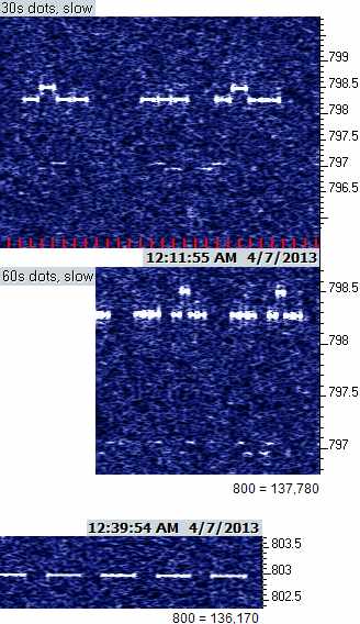
Posted by John VE7BDQ on April 07, 2013 at 03:51:51.
FYI VE7BDQ on again tonight sending 90 second dashes until approximately 07_0700z or later ~ 136.173 kHz
73 John / VE7BDQ cn89la
Re: 2200m
Posted by John Davis on April 07, 2013 at 07:33:44.
In reply to 2200m posted by John VE7BDQ on April 07, 2013
It was like Canada Night, eh, from one coast to the other.
I tried for DK7FC around sunset because it was coming in well Back East, but QRN was too rough here in SE Kansas. Once the static levels died down for the night, however, conditions were pretty good from Up North. VE7SL and VO1NA were also on screen, as seen below. (Even had decent results at 1750 meters over a few hundred miles as well.) Don't let anyone tell you otherwise...DX is truly possible in April, too!
John
Re: Ground Radials and Concrete Rebar
Posted by John Davis on April 08, 2013 at 04:30:18.
In reply to Re: Ground Radials and Concrete Rebar posted by Lee on November 22, 2012
Lee, I ran across something tonight that may not exactly answer your earlier question, but it seems to hint at a positive result, anyway:
http://www.scott-inc.com/html/ufer.htm
John
Re: Ground Radials and Concrete Rebar
Posted by Pat Bunn on April 08, 2013 at 14:39:09.
In reply to Re: Ground Radials and Concrete Rebar posted by John Davis on April 08, 2013
Ufer grounds are excellent at power line frequencies. We use them often in designing power system grounding. They tend to test much better than ground rod systems.
Pat Re: Ground Radials and Concrete Rebar
N4LTA
Posted by EdWSlidell,LA on April 08, 2013 at 14:40:11.
In reply to Re: Ground Radials and Concrete Rebar posted by John Davis on April 08, 2013
Hello Lee and John D. One really extreme example of bonding the rebar is the extent of grounding at astronomical observatories. As they are sited on high eleveation areas, they are subject to frequent lighting strikes. One in particular that I have seen is at McDonald Observatory, near Ft. Davis, TX. I looked at the base foundations for the large 82" and 107" telescope domes and there were large(4/0) stranded wire cables going into the mountain top(Mt. Locke). These came out every 15 ft. or so, and appeared to be made of a bronze alloy. With all the sensitive equipment used this is likely a real necessity. I have asked concrete people about welding the rebar where they cross, but they recommended only using the tiewires. Tacking may pull apart when he concrete sets, and if full welding is done, cause the concrete itself to develop cracks. EdWSlidell,LA EM50cg
Re: Ground Radials and Concrete Rebar
Posted by Pat Bunn on April 09, 2013 at 00:29:58.
In reply to Re: Ground Radials and Concrete Rebar posted by EdWSlidell,LA on April 08, 2013
We specify cad-welding for connecting the copper wires to steel rebar. This is a process in which molds are used with a chemical cartridge which is fired to make a welded connection to steel. Many different molds are available for connection to different steel pieces.
Rebar is never welded at cross connection because if welded it would distort with temperature changes especially with large mats of rebar.
Re: Ground Radials and Concrete Rebar
Posted by EdWSlidell, LA on April 09, 2013 at 01:39:14.
In reply to Re: Ground Radials and Concrete Rebar posted by Pat Bunn on April 09, 2013
Hi Pat. I beleive that the process you mention is also used on vessels whenever anything has to bonded to the deck, such as when anything on a hinged mounting is installed. The special process prohibits any chipping or the like from being done. What I do wonder is whether there is any disimilar metal corrosion within the concrete from the copper/steel joint? Does the process encapsulate the welded joint as it does on a vessel's deck? Prior to this "cad-welding" process, the engineers favored brazing a piece of copper bar to the top of a 4"-6" piece of flat bar steel, and then welding the steel to the deck. Direct connection of the copper strap to steel really produces a bad joint in a short period of time. Current building codes around here now seem to require a stainless seel ground rod, to avoid problems with rebar corrosion. At $85 apiece they are a lot more expensive than galvanized or copper sheathed rods. Ed WSlidell, LA EM50cg
Re: Ground Radials and Concrete Rebar
Posted by Lee on April 09, 2013 at 05:06:47.
In reply to Re: Ground Radials and Concrete Rebar posted by John Davis on April 08, 2013
Very interesting. Thanks for that. Makes me want to rent a concrete saw and expose 4 or 5 bars for bonding. Re: Ground Radials and Concrete Rebar
Lee
Posted by Pat Bunn on April 09, 2013 at 22:03:13.
In reply to Re: Ground Radials and Concrete Rebar posted by Lee on April 09, 2013
Here's a video of a cad weld shot on U tube
http://www.youtube.com/watch?v=M7sB6Hx0kwY
Connecting copper conductor to copper plated steel ground rod
USC back on air
Posted by Pat Bunn on April 11, 2013 at 01:37:57.
Finally got around to checking out USC. Had a bad L317 voltage regulator which changes the voltage to the Epson oscillator to shift the frequency. Not sure why it failed but it was oscillating and the oscillator chip didn't like it at all. The keyer PIC uses a seperate regulator, so it was working fine. New one seems to fix it so, it is back on the air. Frequency may be changed very slightly.
Pat Re: Ground Radials and Concrete Rebar
N4LTA
Posted by Lee on April 11, 2013 at 08:59:32.
In reply to Re: Ground Radials and Concrete Rebar posted by John Davis on April 08, 2013
So I had this idea of cutting the concrete to get to a couple of re-bars. But then it hit me! Per a statement from the Ufer ground web site. Said statement follows.
"He had determined that concrete was more conductive than all but the best soil, and that this improved semiconducting characteristic would enhance surface area contact with the surrounding soil."
Holy ground improvement Batman. Cutting up my patio with a concrete saw is No Bueno with the spouse. So how about this. Installing a 2 or 3 square foot or bigger plate of copper to the concrete with fasteners and some kind of conductive product. Then bonding that plate to the ground rod/radial system. Since the writer of this piece claims that concrete and rebar has a lower resistance than the worst soil { my location } just coupling to the concrete surface might help. I love the way problems percalating in my head and just pop up with possible solutions while I am duing somthing else. Re: Ground Radials and Concrete Rebar
Lee
Posted by Pat Bunn on April 11, 2013 at 13:10:58.
In reply to Re: Ground Radials and Concrete Rebar posted by Lee on April 11, 2013
Copper plate is pretty expensive. You may be just as well off by dowelling a small pad extension along the edge of the existing patio (it could be underground so it wouldn't show) on to the edge of the existing pad with rebar or even 1/2' copper pipe.
Drill hole into the side of the pad and insert the dowels and pour the extension. I would think the more contact area the better - like a 6" extension along the whole side would be better that a bigger pad. The deeper the dowel holes the better.
Pat
Re: USC back on air
Posted by Pat Bunn on April 11, 2013 at 23:39:30.
In reply to USC back on air posted by Pat Bunn on April 11, 2013
It failed again so I suspect that the Epson programmable oscillator is bad. I have a spare, but since it's down, I am rebuilding a new circuit board and putting it in a permanent enclosure. May be down a few more days.
Pat
Re: Ground Radials and Concrete Rebar
Posted by Lee on April 12, 2013 at 05:52:50.
In reply to Re: Ground Radials and Concrete Rebar posted by Pat Bunn on April 11, 2013
Interesting. I'm mulling over some ideas including yours. What ever I do needs to be low key, [spouse doesn't complain], not complicated, [spouse does not see it] and easy [can install in a day]. I'm leaning towards a copper strap from a marine parts supplier bolted with small red/heads to edge of the patio nearest the ground rod. Thanks USC is Back OnThe Air With New Oscillator
Lee
Posted by Pat Bunn on April 16, 2013 at 00:16:00.
Built a new PC board for the USC beacon and it is back on the air. Reports would be appreciated. Replace the Epson oscillator that had failed. It will soon be mounted in a temperature controlled box to make it more stable.
Pat Re: USC is Back OnThe Air With New Oscillator
N4LTA
Posted by Garry, K3SIW on April 16, 2013 at 00:53:02.
In reply to USC is Back OnThe Air With New Oscillator posted by Pat Bunn on April 16, 2013
Pat, I just shut down my hifers to take a look. See NC decently with the sq wave low freq at 13555555 Hz. EH FSK is strong with the low freq at 13555446 Hz. TAG has returned (was RY) sending QRSS(10?) at 13555413 Hz. I don't see USC for sure but there is something sending DFCW just below NC; the low tone is 13555545 Hz. Haven't calibrated for awhile so the frequencies may be off somewhat but the frequency differences should be accurate.
73, Garry, K3SIW, EN52ta, Elgin, IL
Re: USC is Back OnThe Air With New Oscillator
Posted by Pat Bunn on April 17, 2013 at 00:24:12.
In reply to Re: USC is Back OnThe Air With New Oscillator posted by Garry, K3SIW on April 16, 2013
Garry,
I just had time to measure the USC frequency. It is considerably lower than I expected. I measure the high frequency at approximately 13.55533075 and the low tone is approximately 13.55532820. This leaves me 227 hz lower than NC and out of the window. I doubt that I can pull the oscillator up that much but I will try and see what happens.
Pat Re: USC is Back OnThe Air With New Oscillator
N4LTA
Posted by Garry, K3SIW on April 17, 2013 at 01:43:24.
In reply to Re: USC is Back OnThe Air With New Oscillator posted by Pat Bunn on April 17, 2013
Pat, I wondered if I missed USC because I wasn't tuned to the right frequency. Sure enough. Tonight the signal is plenty strong, along with NC, EH, and TAG (understandably weak due to the temporary antenna setup). I've posted a screen capture on the LWCA Reception & Loggings forum - http://lwca.org/community/YaBB.pl?num=1366162580.
73, Garry, K3SIW, EN52ta, Elgin, IL
Re: USC is Back OnThe Air With New Oscillator
Posted by pat bunn on April 17, 2013 at 21:18:10.
In reply to Re: USC is Back OnThe Air With New Oscillator posted by Garry, K3SIW on April 17, 2013
I ordered a couple of oscillators last night from DigiKey and as soon as they come in, I'll get it back in the right place.
Pat Hard Limiter
N4LTA
Posted by John Bruce McCreath on April 18, 2013 at 14:24:16.
Hi John, LWCA,
I built a variation of your audio hard limiter and am pleased with the performance. I use a Timewave DSP-59+between my LF/MF receiver and the computer, but was having trouble with strong signals causing the "Overload" LED to come on. The hard limiter connected between the receiver and the DSP has solved this issue for me. Obviously, I left out the filter components and just used the front end of the limiter and a pot to set output level off of point A. Thanks for sharing the circuit with us!
73, J.B., VE3EAR Re: USC is Back OnThe Air With New Oscillator
Posted by Sal,K1RGO on April 19, 2013 at 14:43:25.
In reply to USC is Back OnThe Air With New Oscillator posted by Pat Bunn on April 16, 2013
At 15:00 utc, I got a good copy on USC on ~ 13.555530 today. Your oscillator is working. Hifer on a budget
Later dude..... Sal
Posted by Krystallo on April 20, 2013 at 15:50:44.
Hey All,
Just curious, what Tx(s) are READY or VERY EASILY modded for Hifer "on a budget", and also which keyers are suggested.( MFJ ?).
I THINKING about having a "Plain Jane" CW beacon , nothing fancy and don't want to build (if I can avoid it)-I have FAR too many projects on the bench as is and not enough free time away work/family to get to them nearly fast as I would like.I'd also like a "moderate" toward "low cost" set up.
Just kind of "doing homework" for now, nothing definite.
Also, for lack of a better term, do you guys try to "coordinate" frq uses within the LWC (maybe you're the ONLY folks doing Hifer anyways ) ?
Side note , Now a General after 20 years as a Tech ( which was probably a world record, Hi).
de K
Re: Hifer on a budget
Posted by John Davis on April 20, 2013 at 20:53:27.
In reply to Hifer on a budget posted by Krystallo on April 20, 2013
I'm not aware of any readily available devices that are easy to modify for HiFER use, but there are some very inexpensive options that don't require much time at all. A lot of the group utilize some variation on Lyle Koehler's Epson programmable oscillator transmitter, first described in a series of articles in The LOWDOWN concerning the use of protoboard in working up useful and viable LF, MF, and even HF circuits.
We've had an online version of the material for some time...so long, in fact, that a few points are now outdated, and I need to make a few revisions to bring everything up to date. The radiated signal limit for HiFER operation has been changed since then (now 15,848 uV/m at 30 meters). Some of the links don't work, the listed ID chip has been replaced by the K-ID2, etc., but a few minutes with Google will get you the correct address for the various Web sites. (Update: The new K1EL site for ordering the keyer chip is now www.hamcrafters.com as of early 2014.)
As Lyle noted back then, prototyping board is not ideal to ensure the full harmonic attenuation required in this band, but most guys have built it on plain PC board material easily enough. Two chips (three if you're not already working from a regulated supply) and a few resistors, coils, and capacitors from DigiKey or Mouser will have you ready in practically no time, and for a VERY low cost! Here's the article as we currently have it:
The Epson oscillator modules have more than enough output and require no additional amplifier, but there is one drawback: they drift a bit with temperature swings, enough to be a nuisance even when using QRSS. There's nothing in the FCC Rules for this band limiting the transmission line, however, so you can have the transmitter inside and use coax to the antenna. And there are other options. In another past LOWDOWN article, Lyle showed how to use a positive temperature coefficient (PTC) thermistor as a heating element to stabilize temperature for a crystal. Or, there's Steve Olney's solution, involving a negative-coefficient thermistor in series with the power supply of the Epson programmable oscillator module.
In this message board last spring, he mentioned a discussion of the idea on his blog, which unfortunately is no longer available. I reported in The LOWDOWN on my own preliminary experiments with it. Unfortunately, following up did not produce the expected results, and a little afterthought suggests maybe it should have been a PTC thermistor instead. I have therefore removed the link to the PDF of my former comments from this post.
The only frequency coordination process most HiFER operators use is to find a spot where someone is not currently operating, according to our online list. Apart from a few would-be "broadcasters," who may not even be aware of us, most Part 15 users of the HiFER band do seem to be dedicated experimenters who keep us well informed of their activities. (Of course, you probably also don't want to operate within a couple kHz of 13.560 MHz itself, due to the noise levels. You may notice that nobody in this board has yet reported any of the stations that have tried that spot in the past. Even at my listening post out in the country, there's too much racket right at the center of the band. Plus, afternoons are pretty noisy in the upper half of the band due to the SWBC on 13.570 splattering sidebands all over the place; but at least that usually ends while the band is still reasonably active.)
I hope that's enough information to get your creative juices flowing.
John
Re: Hifer on a budget
Posted by Ward Wheaton on April 21, 2013 at 02:41:46.
In reply to Hifer on a budget posted by Krystallo on April 20, 2013
K,
If you just want to do plain old CW, I have a PIC based homebrew keyer I'll donate to your project. Nothing fancy, not qrss, but a simple keyer that will key an Epson chip just fine. I'm using the same thing in the AJO beacon. Just let me know what you want it to send.
Re: Hifer on a budget
Ward K7PO
Posted by Krystallo on April 21, 2013 at 12:36:03.
In reply to Hifer on a budget posted by Krystallo on April 20, 2013
Hey Guys,
Thanks for all the info.
Ward: I GREATLY appreciate your offer. I just don't want to put you out, especially if the keyer is worth ANY sort of money (along with the cost of shipping). Perhaps an "arrangement" can be made as we go along . If you care to pop it in the mail, that would be VERY kind.Any data sheets,schematics,WWW links or instructions,etc, would be helpful.
John: Which way did the Hifer power go - up or down ? What is the current allowable radiation level AS MEASURED IN mW (from a 1/2 wave dipole)?
FWIW, my buddy is the master radio tech for a large agency here in Boston and he's thinking of putting up a 10 M beacon, so while "everyone" is on a beacon kick perhaps he could also help me along a bit with a Hifer.
I'm sure I could probably perf a chip or two, I just can't get into anything TOO involved w/numerous discrete components.
I have done "ultra" to "super" low FM and SSB QRP on 2 M and 70 CM but so far not on HF.
What kind of report do you guys get?
Is Hifer reception "reasonably common" -OR- "fairly" (maybe even "very" ) rare at such low power ,especially w/ "conventional" ham beacon CW ?
The "up" side I can think of is 13 Mhz "should" be a GREAT place on HF to do this because of "expected " good propagation there.
tnx de N1NQC
Kevin "Krystallo" Norton
12 Carol #5
Brighton, MA 02135
Re: Hifer on a budget
Posted by Krystallo on April 21, 2013 at 13:04:19.
In reply to Re: Hifer on a budget posted by Ward Wheaton on April 21, 2013
Hey Guys,
Ward : It would be VERY kind of you to send the keyer. I don't want to put you out though, so perhaps some type of "arrangement" can be made as we go along.Any kind of data you can send would be helpful ( the schematic, WWW links, etc)
John, I wonder - Did the power level go UP or down ? What is current limit to a 1/2 dipole as measured in mW ?
I can find some time do a few chips on a perf, I just couldn't get into anything too big right now.
What type of reports do you guys get? Is "REGULAR" CW Hifer reception "common" or very rare ? Are there any links or schematics for the Chip based tx you spoke of ?
Quick Off topic , Also (as time allows) currently building "high Q" 9' X 9' loop and a " high Q" 5' X 5' loop, both capable of "LF" ( 120 or 150 Kc ?) to "HF" (8 or 9 Mc ?). I'll also be going for Tweeks,etc, (w/o var caps,maybe w /choke) on the big one . Both mostly done.
More to follow.....
de K
Kevin Norton N1NQC Re: Hifer on a budget
12 Carol Ave # 5
Brighton, MA 02135
Posted by Pat Bunn on April 21, 2013 at 17:05:18.
In reply to Re: Hifer on a budget posted by Krystallo on April 21, 2013
If you are serious about putting a HIFER on the air, I'll send you a PC board with a PIC programmed with your ID at QRSS3 set up for frequency shift keying. You need to add an Epson oscillator available at DigiKey for $5 plus shipping. The oscillator feeds a 100 ohm trimpot to set the power out. The board requires three trimpots, a 2n3904 transistor, a 78L05 regulator, a LM317L regulator, a few resistors and three T37-6 toroid cores and a few caps. I'll supply those also if you are serious.This will feed a dipole or vertical nicely.
I probably should do an article for the Lowfer if John is agreeable.
Re: Hifer on a budget
Pat
N4LTA
Posted by John Davis on April 21, 2013 at 21:18:24.
In reply to Re: Hifer on a budget posted by Pat Bunn on April 21, 2013
>>> I probably should do an article for the Lowfer if John is agreeable.
Yes, please! :-)
Re: Hifer on a budget
Posted by John Davis on April 21, 2013 at 21:47:34.
In reply to Re: Hifer on a budget posted by Krystallo on April 21, 2013
John, I wonder - Did the power level go UP or down ? What is current limit to a 1/2 dipole as measured in mW ?
Up, fortunately. It is equivalent to approximately 4 mW at the input of a dipole nowadays. (That's peak power, by the way. No difference for CW, FSK, etc., but anyone who has ambitions of AM or other modes where the power varies with modulation needs to keep that limit in mind.)
What type of reports do you guys get? Is "REGULAR" CW Hifer reception "common" or very rare?
Regular speed Morse reception is not exactly rare, but it's certainly not an everyday matter either, the way QRSS3 and related slow modes are. I can see the signals employing slow graphical modes virtually any afternoon that I can get out to my field, but the regular CW signals require a lot more listening time to snare usable IDs. The slow modes, up to about 3 seconds bit length, are vastly more reliable. But plain CW still works at times.
Ward's AJO beacon is one of my benchmarks, for instance. I can hear it for a few repetitions at a time during approximately a third to half of my listening sessions. Some days I leave Argo running on the notebook computer as I listen by ear, and frequently I can see AJO's dash-after-ID on screen even if I can't yet hear the signal. That lets me know to keep listening, and eventually the ionosphere rewards my patience. MTI sends at about 5 wpm, which is also able to give me a trace on Argo before I can actually hear the Morse itself. GNK, FRC, and others sometimes can be "sensed" that way before reaching audibility, too.
Use the "Msg Board Search" button near the top of the main Message Board page and search for "hifer" if you'd like to see some of the typical past reports that have been posted here.
Are there any links or schematics for the Chip based tx you spoke of?
You've probably noticed by now that Lyle's schematic is in the live link in my first reply to your question. The current K-ID2 IDer chip has minor differences in pinout and message storage capacity, so you would want to read the data sheet and modify that circuit slightly. (It can be factory programmed for either QRSS or CW, or even both in the same message.) Their website is: http://www.k1el.com/
John
Re: Hifer on a budget
Posted by Krystallo on April 21, 2013 at 23:41:59.
In reply to Re: Hifer on a budget posted by Pat Bunn on April 21, 2013
Hey Pat,
Here's my 'sad story": I agree that QRSS (et al) is by FAR a better way to go.
My problem is that we have only ONE computer in the house and it is way out in the dining room - NO WHERE CLOSE to the ham shack. Admittedly , I am also kind of "old school" and not TOO much into computers anyways . I am not "ultra proficient" with them .
So if I went the "smart " way and used QRSS instead of "normal" CW I would simply not be able to hear it for testing or adjustment purposes with my test gear , (etc).
Although I WOULD like to do this, at the same time I should really avoid the temptation to "get in over my head" w/ QRSS, even if it IS a MUCH better way to go.
Your comments ?
K
Re: Hifer on a budget
Posted by Pat Bunn on April 21, 2013 at 23:50:51.
In reply to Re: Hifer on a budget posted by Krystallo on April 21, 2013
Not sure why you think you need a computer? This is all on one 2" x 1 1/2" board including the QRSS3 keyer. You certainly don't need a full blown PC to generate QRSS3 keying. It is all done in a 8 pin PIC 12F509A chip.
All that you need to make it go is 12 volts at .1 amp or so and an antenna.
Re: Hifer on a budget
Posted by John Davis on April 22, 2013 at 06:47:21.
In reply to Re: Hifer on a budget posted by Pat Bunn on April 21, 2013
I agree with Pat. It's nice to be able to monitor QRSS on a computer screen, but it's not an absolute necessary at the sending end. If you aren't sure about the keyer functioning properly, you can always verify proper keying by ear quite readily at QRSS3, for instance. (Slower modes become awkward, but 3 second dots aren't difficult to follow.) Don't let that deter you from being heard over greater distances.
John
Re: Hifer on a budget
Posted by Krystallo on April 22, 2013 at 12:00:50.
In reply to Re: Hifer on a budget posted by John Davis on April 22, 2013
Hey Guys,
I have to admit ignorance about QRSS (it seems to have shown here, hi). I have ZERO experience and near zero knowledge of it.
I knew that computers were (generally ?) "used" at the receive end,but I was unsure on whether there was any type of digital "encoding " on transmit- apparently not.
So if I have this right, at the transmit end QRS"S" is nothing more complex than a "conventional" CW type oscillator being keyed at super long dits and ultra long dahs- correct ?
If (IF !) that is the case , than in THEORY one could possibly grab a super low powered QRP 20M rock bound rig and slap in a Hifer xtal.
I IMAGINE that the "stretch" from the low end of 20 M down to Hifer( < 500 Kc) wouldn't be 'too much" and the rig 'should" still function.
Then the only thing left in the shack end is to get it keyed at whatever rate is suggested.
ANTENNAS are a whole other issue, but I drew up an idea or two last night.
K
HiFers Heard 21 April, 2012
Posted by EdWSlidell,LA on April 22, 2013 at 13:21:30.
Hi all. I was able to listen on the band yesterday, 21 April, around 2200-2300UT. MTI on ~13557.5KHz was just audible at times. At maximum it was reaching 339, but mostly was near the limit of audibility, or inaudible. SZX around ~13563KHz was doing much better, reacing around 449 when peaking. It never did fade out completely, although the QSB took it down to the noise at times. Did not hear GNK or K6FRC during this period. Ed WSlidell, LA EM50cg
Re: Hifer on a budget
Posted by John Davis on April 22, 2013 at 18:10:14.
In reply to Re: Hifer on a budget posted by Krystallo on April 22, 2013
So if I have this right, at the transmit end QRS"S" is nothing more complex than a "conventional" CW type oscillator being keyed at super long dits and ultra long dahs- correct?
To quote the late Ed McMahon, "You are correct, sir!"
For normal QRSS3 (about the slowest you want to key Morse characters at 22 meters, because propagation fluctuations tend to break up longer elements and thereby turn dashes into false dots) the length of a dit is 3 seconds, the length of a dah is 9, the spacing between consecutive dits or dahs is 3 seconds, and the spacing between letters is 9 seconds...the same 1:3 ratios that apply for conventional Morse, in other words.
For slower QRSS modes, folks may cheat a little in order to save transmission time. There is at least one computer program that will generate dashes that are only twice the length of a dot, for instance, or which cut the interword spacing to only the length of two intercharacter spaces. But that can be confusing to read if you're not expecting it, and it's totally unnecessary at a mere QRSS3. Just slow a conventional keyer down to 0.4 WPM, assuming it will let you, and you're good to go.
(Digression: Another way folks have tried to save time when running QRSS30 or 60 is by changing the weighting of their keyers, shortening the spaces between elements. Don't even be tempted to do that with QRSS! It's a false economy. What they are forgetting is that Argo, the most common viewer for QRSS and related graphical mode, is a matched filter system. That means the width of the FFT bins used for detection, and the time over which their energy levels are integrated, are customized for each speed setting. Their response is chosen to match the time and frequency characteristics of the shortest element length used in the selected speed, and therefore have optimal response to a squarewave in which the ON and OFF intervals are both equal to that shortest element length...or an integer multiple thereof. If you were to send a continuous string of EEEEE at 12 WPM standard Morse, for instance, it would be a squarewave train of 0.1 second on, 0.1 second off. For QRSS3, the same string would be 3 seconds on, three off. Which is great because the matched filter time response, being inherently symmetrical, has maximum response to such sequences. If you shorten the spacing, then you only get maximum detection if you also change the detector settings to match the shorter time interval...which then means you must actually run the detector in a faster, less efficient mode for clarity, so all you're really doing is wasting the longer ON time. In short, "just say no" to non-standard weighting when running QRSS.)
...one could possibly grab a super low powered QRP 20M rock bound rig and slap in a Hifer xtal.
Yes, if a person has one of those, it can probably be made to work just fine.
You'd want to be sure you have a way to trim the power, of course, and you'd want to incorporate an additional low-pass filter like the one in Lyle's design. Harmonic suppression requirements for this band used to be much tighter than is required for ham gear. Now it's apparently only -34 dBc, but there are some QRP rigs out there that don't actually achieve even that much. Better safe than sorry.
Speaking of rules, just for reference, here's the section (15.225) that applies inside the 22 meter band itself.
ANTENNAS are a whole other issue, but I drew up an idea or two last night.
Best advice there is: keep it simple.
The actual limit is on radiated field strength in the maximum lobe, remember. So if you do anything that gives you more gain (in any direction) than a plain dipole, you have to cut transmitter power by an equivalent amount! Therefore, your best bet is generally to try to keep it as nearly omnidirectional as possible.
In my book, the ideal would be a quarter wave whip with its base a half wavelength above ground, employing 45° drooping radials. Good match to 50 ohms that way, and the same gain as a dipole, but fully omnidirectional and a reasonably good radiator for low-angle skywave.
It's not the easiest structure to build in all locations, however, so some folks use verticals that aren't as high up (just try to avoid situating the base right at a quarter wavelength above ground). Some even use surface mounted verticals over a ground screen, but because of the theoretical pattern gain of a monopole, they have to use roughly half the power. Still works OK, apparently.
Others use actual dipoles, of course. The only drawback is the directionality. You'll always have at least some potential listeners in or near a null. My personal choice, if I were stuck with using a dipole, would be to either form it into a ring for the sake of omnidirectionality, or else to employ two dipoles crossed at 90 degrees and fed in phase quadrature. The latter turnstile arrangement, if both the 90° physical alignment and 90° RF phasing can be assured, would let you feed both dipoles with 4 mW and still meet the signal strength limit in an omnidirectional pattern.
Just a few ideas to consider....
John
Re: Hifer on a budget
Posted by Krystallo on April 22, 2013 at 20:34:30.
In reply to Re: Hifer on a budget posted by John Davis on April 22, 2013
Hey John,
I SCOURED the net looking for a simple low powered 20 M rock tx- either as a kit or pre built. Didn't see ANYTHING I liked-LOTS of stuff for other bands, especially 40, but nada for 20.So kind of back to square one for now.
Re ant: I have an existing "receive only" sloping "T" shaped "7" M dipole fed at 90 deg w/ RG -8x(antenna's actual specs = around 75 ohm / 1.5 : 1 SWR ?). I wanted to use for VHF low band scanner skip / 10 M rcve.
But the F MUF hasn't really gone up too high to often and this ant was kind of a bust.I think the cycle doesn't have too much left either before the "peak" (if you want to call it that). Probably "some" E skip coming up ("at times") this summer , but maybe no long dx F support.
So I may "extend" each leg helicaly on PVC for a Hifer tx.Not the greatest idea going, but is space limited and all the good supports on my flat apt roof are already taken.
Cannot do a vertical.
K
13.555 kHz activity Apr 23, 2013 in NE IL
Posted by Garry, K3SIW on April 23, 2013 at 15:23:58.
Just posted a screen capture of 13.555 kHz watering hole hifer activity this morning to LWCA Longwave Community � Screen Captures, Station Photos, Documents � Reception & Loggings (http://lwca.org/community/YaBB.pl?num=1366730441/0#0).
73, Garry, K3SIW, EN52ta, Elgin, IL
GNK down for about a week
Posted by Domenic on April 23, 2013 at 15:43:29.
Hello all, The GNK beacon on 13.564 will be down for about a week so a new roof can be installed. I will message this board as soon as the attic antenna is reinstalled and the swr is reset. Re: GNK down for about a week
Domenic
KC9GNK
Madison, WI
Posted by EdWSlidell,LA on April 23, 2013 at 19:32:07.
In reply to GNK down for about a week posted by Domenic on April 23, 2013
OK Domenic. Was able to listen yesterday in the PM, and MTI around 13557.5, SZX around 13563, GNK around 13564, and K6FRC around 13565 KHz, were coming in. All were better than my previous posting, in the 3/4-3/4/-9 signal range. Conditions must have improved since this weekend. Hopefully they will not be using any foil undercoating. Will be listening for your return. Ed WSlidell,LA EM50cg
Re: Hifer on a budget
Posted by Ward Wheaton on April 24, 2013 at 16:32:45.
In reply to Re: Hifer on a budget posted by Krystallo on April 21, 2013
Kevin,
No problem, I'll be glad to send the keyer to you. As I said, just let me know what you want it to send. After reading the replies, I think you'll have better luck with the offer from Pat, N4LTA since it sounds like a very easy way to put a beacon on, especially with a ready made pcb. It's up to you, just let me know. I will be out of town most of May (Dayton Hamvention) so it would probably be early June before I can get it out to you, unless you decide in the next couple days.
As for QRSS, I'm kind of old school about it myself, although it's not a problem to copy QRSS3 'live', just boring. However, after seeing the advantages, I'm going to add QRSS to my keyer chips.
Ward K7PO Re: Hifer on a budget
Tonopah, AZ
Posted by John Davis on April 24, 2013 at 20:48:28.
In reply to Re: Hifer on a budget posted by Ward Wheaton on April 24, 2013
>>> ...although it's not a problem to copy QRSS3 'live', just boring.
That's a good way to put it. :-)
Glad to hear you'll be making it to Dayton. Will you be monitoring enroute again this year?
John
Re: Hifer on a budget
Posted by Krysta;llo on April 25, 2013 at 11:58:08.
In reply to Hifer on a budget posted by Krystallo on April 20, 2013
Hey Ward,
Indeed, if Pat's unit is an "all in one" I don't think I'll need two keyers. Thanks for your kind offer though. I don't want anyone to bother to send anything that is redundant.
K
Re: Hifer on a budget
Posted by Ward Wheaton on April 25, 2013 at 17:10:10.
In reply to Re: Hifer on a budget posted by John Davis on April 24, 2013
John,
Yes, I'll be monitoring along the way. We're taking the more northern route this time, I-40 as opposed to I-10 down south, so it will be interesting to see what's different. There are some places along I-10 in Texas, one being just outside of Kerrville, that I have heard AJO on every trip.
We have the luxury of taking an extended road trip this year, and I am extraordinarily blessed to have a licensed (KD7NW) and very radio tolerant XYL. She even does the driving chores when I want to play radio!
-73- Help ID NDB spotted in Cima Ca
Ward K7PO
Posted by Lee on April 26, 2013 at 04:34:57.
I made a Vegas run on Monday this week. Close to the Nevada state line I spotted a NDB setup that looked exactly like the NDB beacon I see at Bob Hope airport, Burbank CA. Need some help ID'ing it. It would be a perfect local target to prove receive capabilities. Per google maps [Google maps is awsome] it is located in Cima CA. Located at 94267 Clark Mountain Road, Cima CA 92323. The location looks like some kind of goverment maintenace yard. State or Fed I can't tell. I can't read the site signage. Any pointers to a data base would be great. Tried Google FCC hits but without the freq I got a lot of usless admin data. Thanks! Re: Help ID NDB spotted in Cima Ca
Lee
Posted by John, W1TAG on April 26, 2013 at 15:13:18.
In reply to Help ID NDB spotted in Cima Ca posted by Lee on April 26, 2013
Lee,
Looking at the aerial and street views of that location, it looks more like a highway maintenance depot off Rte 15, and not an airport. Are you sure that antenna is for an aero beacon, or could it be for a TIS (Travelers Information Service" transmitter? TIS info is usually broadcast in the 1600-1700 kHz range, or possibly at 530 kHz. Some searching with an AM radio should find a strong signal, if this is the case.
John, W1TAG
Re: Help ID NDB spotted in Cima Ca
Posted by Lee on April 27, 2013 at 05:34:36.
In reply to Re: Help ID NDB spotted in Cima Ca posted by John, W1TAG on April 26, 2013
Good point. I did not see any TIS info signs so I don't think it was one of those. But don't know for sure. I have seen some TIS rigs/traffic condition stations around town here and they are usually around 10 watts and use a big whip with a long 5 or 6 inch base coil. The only thing I am certain of is this rig matches exactly the rig on Hollwood Way Blvd at the entrace of Bob Hope airport in "Beautiful Down Town Burbank". Re: Help ID NDB spotted in Cima Ca
Lee
Posted by Lee on April 27, 2013 at 07:27:16.
In reply to Help ID NDB spotted in Cima Ca posted by Lee on April 26, 2013
Update / clarification. The actual address for the site is 94267 Clark Mountain Road, Nipton CA 92364. The site is not in Cima CA per Google maps. The nearest offramp is in Cima CA so I assumed that city was the home to this address. Not so. I found an FCC data base for TIS stations in CA. I will check that out for " City of Nipton " hits. I also found this " NDB " web site for all known NDB's US and beyond. Will look for this Nipton location as well.
http://www.dxinfocentre.com/ndb.htm
Re: Help ID NDB spotted in Cima Ca
Posted by John Davis on April 28, 2013 at 17:11:02.
In reply to Re: Help ID NDB spotted in Cima Ca posted by Lee on April 27, 2013
The Google Street View image for the Nipton site is not nearly as sharp as the one for Bob Hope Airport. Do you remember, Lee, if the Nipton antenna had horizontal top load elements like the one at Bob Hope? The open sphere or ring at the top is certainly similar, as is the type of mast and the box at the base.
There are several manufacturers of TIS/HAR transmission systems, and I'm not familiar with this particular one, but I'd almost bet it's a TIS facility in both cases. Very likely one would be able to tune around the AM dial in Burbank and find parking information for the airport, and perhaps weather information for the mountain pass at Nipton.
There are some similar looking NDB installations in various parts of the world, but these do not appear to be in the kind of locations where an NDB would typically be installed. The one in Burbank looks to be situated in a fenced enclosure at the corner of a parking lot very near the boulevard, for instance, where it is not likely that they would be able to install the kind of ground system that is standard practice for NDBs.
A TIS (Travelers Information Service) station, operating at a higher frequency and not requiring the same miles per watt as an aerobeacon, can get by with a lesser ground than an NDB. On the other hand, a TIS is usually intended to provide information to a specific area over a long span of time, so even if the ground system is not very elaborate, the mast and transmitter enclosure are both generally built to be very sturdy.
A typical HAR (Highway Advisory Radio) station, normally being more portable and used in any one spot for a shorter term, may have as little as a single ground rod beneath it. Those are the ones which tend to be a glorified whip with a conspicuous loading coil, easily transported and set up at another site when needed.
John
Re: Help ID NDB spotted in Cima Ca
Posted by Lee on April 29, 2013 at 04:07:39.
In reply to Re: Help ID NDB spotted in Cima Ca posted by John Davis on April 28, 2013
I think you nailed it John. It is probably a TIS setup both sites. Both rigs have the same 2 sphere tophat at the top of the mast. I was chasing the theory tonight that it was a beacon for the small airport behind the resorts at StateLine. No info to support that. On the bright side I compiled a list of CA beacons 200 to 600 miles away from me. I can use this list to shake down the shielded loop I have in he works. Thanks to everyone. That was fun. GNK back on.
Lee
Posted by Domenic on April 29, 2013 at 23:46:43.
Re: GNK back on.
Hello All, GNK hifer beacon is back on 13.564 with the attic antenna and a new roof. The new roof does not have any foil. Thanks Ed, looked into that before they even got the ladders out.
Domenic, KC9GNK
Posted by EdWSlidell, LA on April 30, 2013 at 01:08:33.
In reply to GNK back on. posted by Domenic on April 29, 2013
Hi Domenic. Looked for your signal earlier today, and noticed it coming in just about an hour ago(0000UT/30 April, 2013). Around about 3/4-3/4-9, almost as strong as, but slightly less than SZX just below you on ~13563 KHz. Also heard the QRQ CW of K6FRC coming in on and off around ~13565 KHz. Earlier in the day, MTI was just audible on ~13557.5 KHz from time to time. Looks like your roof is ISO 9022M certified. Ed WSlidell,LA EM50cg
potrzebie