SAQ Grimeton Transmission on July 4th, 2021
The annual transmission event on the Alexanderson Day with the Alexanderson Alternator from 1924, on VLF 17.2 kHz CW with the call sign SAQ, is scheduled for Sunday, July 4th, 2021.
The Alexander Grimeton Association are planning to carry out two broadcasts to the world from the old Alexanderson alternator SAQ. Only required staff will be in place, due to the ongoing pandemic.
Transmission schedule:
Startup and tuning at 10:30 CET (08:30 UTC) with a transmission of a message at 11:00 CET (09:00 UTC)
Startup and tuning at 13:30 CET (11:30 UTC) with a transmission of a message at 14:00 CET (12:00 UTC)
Live Video from World Heritage Grimeton Radio Station
Both transmission events can be seen live on our YouTube Channel.
The live video starts 5 minutes before the startup and tuning.
https://mailchi.mp/aff85163e64f/alexanderson-day-2021?e=2c0cbe870f
Re: SAQ Grimeton Transmission on July 4th, 2021
Posted by Mike Terry on June 03, 2021 at 20:44:04.
In reply to SAQ Grimeton Transmission on July 4th, 2021 posted by Mike Terry on June 03, 2021
A better link:
https://alexander.n.se/alexanderson-day-2021/
Reminder: Lowfer net +/- 3927 kHz Saturday morning 0800 California time
Posted by Jerry Parker on June 04, 2021 at 13:13:15.
Reminder: Lowfer net +/- 3927Khz Saturday morning 0800 California time
Or listen online at kfs:
http://69.27.184.62:8901/?tune=3927lsb
or
KPH Point Reyes:
http://198.40.45.23:8073/
or
Utah Web sdr:
http://www.sdrutah.org/websdr1.html
If you cannot get into the net on 80 meters you can listen on KFS and participate by sending net control your thoughts to wa6owr@gmail.com
73
New HIFER Beacon
Jerry
Posted by Mike Hayden on June 04, 2021 at 21:07:59.
Hello HIFERS. I have set up a 24/7 beacon under Part 15 on approximately 13.560 MHz CW running abt 4.0 mW into a wire dipole. It is beaconing LSF representing Lucky Sevens Farm, my QTH in FM19js.
73,
Mike AK3F
Cross Country Wireless
Posted by swlem3 on June 05, 2021 at 03:11:38.
Was looking at Cross Country Wireless (UK) for an antenna preamp and attempted to contact their e-mail for additional info. Made two inquiries in the past 3-4 weeks and have received no response. Perhaps this is Covid related, don't know. Just fyi...
Ray
Re: New HIFER Beacon
Posted by John Davis on June 05, 2021 at 07:48:16.
In reply to New HIFER Beacon posted by Mike Hayden on June 04, 2021
Congratulations, Mike, and welcome aboard.
Could you pin down the frequency a little closer for us, though? Twenty-two meters is a fairly wide band for hunting down what is, by definition, a weak signal outside its groundwave coverage area. Thanks.
John Re: New HIFER Beacon
Posted by Mike Hayden on June 05, 2021 at 09:48:25.
In reply to Re: New HIFER Beacon posted by John Davis on June 05, 2021
Thanks, John. The frequency of LSF is about 13,560.374 khz
I will try to pin that down more accurately as I move forward. It's in the hayloft of one of my barns, so I suspect I may have to control it's environment a bit to get good frequency stability.
Re: Cross Country Wireless
Mike
Posted by Robert, VA3ROM on June 05, 2021 at 12:25:10.
In reply to Cross Country Wireless posted by swlem3 on June 05, 2021
Chris Moulding (CCW) is active on his company's groups.io account so I would suggest that you join this group and post any queries there. Or having a look and see if Chris has already answer your question on the CCW groups.io message board.
https://groups.io/g/CrossCountryWireless/
73 Re: Cross Country Wireless
Posted by swlem3 on June 05, 2021 at 13:08:56.
In reply to Re: Cross Country Wireless posted by Robert, VA3ROM on June 05, 2021
Robert, thanks for the info on the io group.
73, Ray
Re: New HIFER Beacon
Posted by John Davis on June 05, 2021 at 16:06:18.
In reply to Re: New HIFER Beacon posted by Mike Hayden on June 05, 2021
Thanks for that update, Mike. I'll give it a try, but I hope you might consider padding the crystal frequency as far below 13560.0 as it will go while still maintaining reasonable stability. A CW beacon amongst the industrial-scientific-medical devices that cluster mainly between 13559.5 and 13562 is a bit like a mouse trying to be heard over a pack of howling wolves. It has been known to happen, but is a quite rare event indeed.
Re: New HIFER Beacon
Posted by Mike Hayden on June 06, 2021 at 10:42:09.
In reply to Re: New HIFER Beacon posted by John Davis on June 05, 2021
John, thank you for that information. I'm here to learn things like that, that is why I am here. I will pull the frequency lower and post the new on.
Also, I see a number of people using WSPR. is anybody using QRSS techniques for cw detection?
Mike
Re: New HIFER Beacon
Posted by Robert, VA3ROM on June 06, 2021 at 14:10:05.
In reply to Re: New HIFER Beacon posted by John Davis on June 05, 2021
I'll second that, John In any large metro area, lots of ISM fobs, debit & c.c. card readers, hospital devices, yada, yada.
The attached image is from N0EMP's KiwiSDR. There's even more congestion in the really large metro areas.
Even an FSK CW QRSS 6 signal isn't going to survice in that kind of RFI din!
For Mike, welcome to the 22 m "cloud" crowd!
---------------------------------------------------------------
![]() File Attachment 1: ISM_13560_kHz_RFI.jpg
File Attachment 1: ISM_13560_kHz_RFI.jpg
Re: New HIFER Beacon
Robert, John, thanks a lot for the guidance. I spent the morning pulling the oscillator and the new frequency is 13,557,227. that's about as far as i can get it without a crystal change. still at 4 mW, and a wire dipole at about 20 feet. i'll give that a whirl for a while and see how it goes.
i took a look at your sdr trace. man, where i live i see nothing like that.
next i'll set up an spare sdr for the band and get a smart plug to control the tx so i can turn it off when i am listening.
mike QRSS Message Programming
Posted by Brian Sarkisian on June 08, 2021 at 17:50:42.
I recently purchased a K1EL K16 chip for sending QRSS30 and QRSS60. I sent an e-mail to K1EL and he wasn't quite sure what the time script would be for QRSS30 and QRSS60.
Is anyone using a K1EL K16 chip for QRSS beaconing or maybe recommend an outboard
keyer for QRSS.
Thank you
Brian, KG8CO
Re: QRSS Message Programming
Posted by Lee on June 08, 2021 at 19:58:20.
In reply to QRSS Message Programming posted by Brian Sarkisian on June 08, 2021
I bought the WinKeyer kit 2011 ish. The HV version. Had a problem doing QRSS 30 and 60 but a firmware update fixed that. Works great. I alternate between QRSS and WSPR on 2200 meters.
Re: QRSS Message Programming
Posted by Garry, K3SIW on June 08, 2021 at 20:11:12.
In reply to QRSS Message Programming posted by Brian Sarkisian on June 08, 2021
Brian, I use a K1EL K12 IC for sending QRSS30 and QRSS60 with my lowfer when near the so-called calling frequency. If the K16 IC is similar it needs to be programmed by a keyer with separate dot and dash, not a straight keyer.
My programming procedure is as follows: 1. power up (unit responds with "R"), 2. hold CMD/MSG1 pushbutton until "R" sounds again (this moves the IC into CMD mode), 3. send "C" (wait for the response "E"), 4. send "10" (get "R" back if accepted; this changes the rather fast default command code speed to 10 wpm, something that's understandable with my poor keying fist), 5. send "S" (wait for "E" response), then send "10" (or whatever speed you want for the keyer transmit speed)(get an "R" response), 6. send "L" (wait for "M" response) then depress the desired MSG button (get a response of "I") and enter message (an "E" response ensues for each character entered), 7. After the last message entry depress the CMD button before "E" is received or a word space of 7 dits will be included, 8. Successful entry of the message and its storage will be indicated by a response of "R".
The above is quite a mouthful and takes some practice to get right. Maybe the K16 has simplified things.
The message I use is "/Q5SIW/Q4SIW/1". That sends my call suffix at QRSS60 followed by the suffix at QRSS30 and repeats indefinitely. My K12 came with a user manual that contains a table of the embedded commands to flexibly create just about any message sequence.
Good luck and 73, Re: New HIFER Beacon
Garry, K3SIW
Posted by Ed Holland on June 08, 2021 at 22:27:44.
In reply to Re: New HIFER Beacon posted by mike hayden on June 06, 2021
East Coast Beacons have made impressive journeys to CA on a fairly regular basis - I'll keep a watch out for LSF,
73s
Ed
Navtex QRM from HD 530
Posted by William Hepburn on June 09, 2021 at 04:33:10.
CHLO-530 Brampton has fired up HD/IBOC. The lower digital sideband covers 515-521 kHz, completely wiping out 518 kHz Navtex. I have no idea how this was approved as Lake Ontario is part of the Ferndale Navtex service area. The HD signal is 1000 watts day & 250 watts night.
Re: New HIFER Beacon
Posted by John Davis on June 09, 2021 at 04:55:08.
In reply to Re: New HIFER Beacon posted by mike hayden on June 06, 2021
Surprised but delighted to hear you could pull the crystal that far, Mike. I may have a chance to try for LSF at the new spot on Wednesday.
As for your question about QRSS, yes, it is quite useful in this band. Most stations around the 13555.4 watering hole use it in one incarnation or another. And I keep two instances of Argo running in QRSS3 at all times, even when monitoring conventional CW by ear, because I can generally recognize individual stations' keying patterns while they are yet well below audibility.
At one time, QRSS, slow DFCW, and related graphical modes comprised the majority of signals on the band. I wish more stations were using it now, but the lack of speed choices in the Black Cat Systems kit has actually set the hobby back in some senses, despite the kit itself having gotten more people active.
IMO, there needs to be an ever-so-slightly more elaborate version with two more IC sockets on board: one to allow use of K1EL's K-ID2 programmed keyer chip in place of the AT Tiny, and another to allow the oscillator to reside in a gate that's not on the same die as the keyed stage and output gates for greater stability. That should only add about $1 to the kit cost, plus a few more for the K-ID2 if an operator decides to go that route.
John
Re: Navtex QRM from HD 530
Posted by John Davis on June 09, 2021 at 05:02:08.
In reply to Navtex QRM from HD 530 posted by William Hepburn on June 09, 2021
That's dreadful, William. The RF emission mask is only supposed to extend 10 kHz from the carrier frequency on either side, so something must be amiss. The "Din of Ibiquity" strikes again!
New Hifer online
Posted by John Collins KN1H on June 09, 2021 at 13:14:31.
Actually an old Hifer reactivated after a 9 year break. NHVT, 13559khz, 9 wpm CW,3.6mw solar-powered, 24/7.
Re: New HIFER Beacon
Posted by Robert, VA3ROM on June 09, 2021 at 22:31:52.
In reply to Re: New HIFER Beacon posted by John Davis on June 09, 2021
The only problem with DFCW is that you use more bandwidth as compared to FSK CW albeit you can send beacon info faster so 6 of one and half dozen of the other.
As for a more elaborate beacon platform I'm going with QRP Labs Arduino transmitter shield. Options to seat either a AD9850/51 DDS or Si5351 and has single band or multiple band RF filter expansion capability.
shop.qrp-labs.com/Shield?search=arduino
And the price is ridiculously low! How on earth Hans can do it is beyond me. When does he even find the time to sleep?
73
Re: New HIFER Beacon
Posted by John Davis on June 10, 2021 at 04:44:09.
In reply to Re: New HIFER Beacon posted by Robert, VA3ROM on June 09, 2021
The only problem with DFCW is that you use more bandwidth as compared to FSK CW
I can't imagine any reason why that would need to be the case. If you're sending at QRSS3 rate, for instance, you can employ a shift of only 4 or 5 Hz for either mode without any impairment whatsoever.
I agree, it certainly is amazing that Hans can sell such great kits so cheaply.
New member, YSO beacon
Posted by Jim Bailey, AJ8S on June 10, 2021 at 10:30:58.
I am a brand new member of this organization. I am now operating a Part 15 beacon on 13563.5 kHz with the callsign "YSO". It uses the Black Cat transmitter and a low sloping dipole. Reports would be welcome. I will take it off the air from time to time so I can listen for other beacons. I have been active on ham radio for 60 years. My main interests are tinkering, antennas, Olivia mode, and some CW. de AJ8S, 73 to all.
Re: New HIFER Beacon
Posted by Robert, VA3ROM on June 10, 2021 at 17:41:26.
In reply to Re: New HIFER Beacon posted by John Davis on June 10, 2021
Ops. Mea culpa. I was thinking about DFCW-idle. Forgot that DFCW is basically FSKCW without a constant on carrier.
Thanks for the memory jog, Dave.
I ordered the Arduino transmitter shield kit along with the Si5351 module but I also have the AD9850 and AD9851 that I can play with too. They are a tad easier to program.
Oh, BTW, QRPGuys has come out with their new Digital Transmitter III Kit. This uses an Uno and Si5351 but has a neat algorithm for converting soundcard audio tones to pure FSK https://qrpguys.com/qrpguys-digital-fsk-transceiver-iii. A bit more pricier than QRPLabs but who says kit building is dead these days?
73, 13.56 MHz Antennas
Robert
Posted by Brian K6STI on June 13, 2021 at 00:10:10.
Four antennas over three types of ground:
http://ham-radio.com/k6sti/hifer.htm
RT� LW off from 15 June for about 2 months
Posted by Mike Terry on June 12, 2021 at 11:39:19.
AN UPDATE:
RT� News - 11 June 2021
RT� will carry out essential maintenance of the Long Wave (LW) transmitter in Clarkstown, Co. Meath from 15th June 2021 for two months during which period RT� Radio 1 will not be available on LW 252. These works are necessary to ensure that RT� can continue to broadcast RT� Radio 1 on LW.
This essential maintenance of the transmitter was due to be carried out in 2020 but was postponed due to Covid-19 restrictions. For the health and safety of those carrying out the works, the transmitter must be switched off for the works period, until Saturday 14th August (estimated). Furthermore, the works must be completed during the summer months when there is better light and weather conditions.
The works will be carried out by RT� Transmission Network (2rn), a wholly owned subsidiary of RT�, responsible for the distribution and transmission of the programme services of RT� radio and television, as well as TG4 television, Virgin Media television and Today FM.
During this period, listeners will continue to have a wide range of choice to access RT� radio services which are available at www.rte.ie/keeplistening.
More here: Re: Navtex QRM from HD 530
https://about.rte.ie/2021/06/11/essential-maintenance-of-rte-longwave-transmitter/
Posted by Garry, K3SIW on June 11, 2021 at 11:10:34.
In reply to Navtex QRM from HD 530 posted by William Hepburn on June 09, 2021
No problem here with CHLO-530 bothering Navtex reception. However, there is a big problem with a digital signal overlapping 518 kHz and raising the noise floor 10 dB. This interference was present the last 2 nights. It probably began earlier and is not a one-time event. The signal spans about 515.1 to 519.7 kHz with a flat spectrum. There is also a narrow signal component a bit higher in frequency that may be associated with the transmission. It's a night-time event, falling back into the normal noise floor as sunrise approaches.
73, Garry, K3SIW, EN52ta, Elgin, IL
Re: Question about part 15 field strength
Posted by Brian K6STI on June 11, 2021 at 12:26:41.
In reply to Re: Question about part 15 field strength posted by Brian K6STI on June 11, 2021
Turnstile of Crossed Inverted Vs
Rather than go through the power calculation again, I noted that far field gain at 40 deg elevation angle for the turnstile is 1.86 dB lower than that for a single V. So the input power needs to be increased by that amount to maintain legal limit field strength. The result is 3.8 mW if 2.5 mW is correct for a single inverted V. This is at the antenna feedpoint. Increase the amount at the transmitter to account for feedline loss. I used the apex as the reference point for field strength distance since current is maximum there.
Here are some radiation patterns (I'll delete these in a day or two):
http://ham-radio.com/k6sti/turn0.gif
http://ham-radio.com/k6sti/turn1.gif
http://ham-radio.com/k6sti/turn2.gif
The azimuth pattern is remarkably uniform. Note that while radiation peaks at about 45 deg elevation, it's not down that much at lower angles useful for propagation at longer distances. For example, at 20 deg it's -3 dB. You'd have to install the antenna substantially higher above ground to lower the radiation much. I picked 30 feet because that height is easy to obtain with a TV push-up mast. The Vs provide top guys. Leg length is 204.5" and 222" for bare #14 copper wire. These lengths do not account for end effects due to wire loops and insulators. The angle of each wire is 45 deg. Feed impedance is 46 ohms resistive with a couple ohms reactance. A 50-ohm feedline will alter the impedance slightly. If you have a VNA, measure the impedance at the transmitter end of the feedline and use the value to calculate the voltage required for 3.8 mW.
Brian
Re: Navtex QRM from HD 530
Posted by Brian K6STI on June 11, 2021 at 12:34:53.
In reply to Re: Navtex QRM from HD 530 posted by Garry, K3SIW on June 11, 2021
Here is the spectrum of an AM HD Radio signal:
http://ham-radio.com/k6sti/amhd.gif
I'll leave this up for a day or two.
Brian
Re: Navtex QRM from HD 530
Posted by Brian K6STI on June 11, 2021 at 13:44:19.
In reply to Re: Navtex QRM from HD 530 posted by Brian K6STI on June 11, 2021
More:
http://ham-radio.com/k6sti/am1.gif
http://ham-radio.com/k6sti/am2.gif
Brian
Re: Question about part 15 field strength
Posted by Ed Holland on June 14, 2021 at 17:38:51.
In reply to [orphan thread] posted by Brian K6STI on June 11, 2021
Interesting analysis - I took a quick look at the models, thank you for sharing them.
I suppose what it boils down to, would be the balancing act of getting the radiation to be a maximum at some favorable elevation, and then working out the power allowable to hit the max field strength.
Re: [orphan thread] part 15 field strength
Anecdotally, For PVC, I first experimented with a 1/4 wave vertical antenna plus radials on the flat roof of the house. This was not especially successful, so I switched to an inverted vee, (straightforward to re-configure with almost the same materials). This setup has brought in reports, but certainly is not heard as reliably as FRC, also in CA.
Posted by Brian K6STI on June 14, 2021 at 18:21:30.
In reply to Re: [orphan thread] part 15 field strength posted by Ed Holland on June 14, 2021
Ed, I got John Davis to delete my posts in this thread. I had posted so many different numbers due to errors, oversights, and updated calculation methods that I thought it would confuse everyone. Look for another thread "13.56 MHz Antennas" that gives no numbers but references a web page I created. Now when I make errors I can fix them! I think you've seen it, but for anyone else, the page is here:
http://ham-radio.com/k6sti/hifer.htm
I've been adding new information to the page that's relevant to your comments. The legal power figures and radiation patterns are hard to interpret by themselves. So I converted the legal power to dB and added it to the peak azimuth pattern value for a number of elevation angles (now up to eight, including 1� for DX). From the numbers you can easily see which antenna works best for each angle.
To figure out what angle you, need see this informative Wikipedia entry:
https://en.wikipedia.org/wiki/Skywave
Check out the graph of elevation angle vs distance for both E and F layer skip.
Brian
Re: [orphan thread] part 15 field strength
Posted by Ed Holland on June 14, 2021 at 19:02:06.
In reply to Re: [orphan thread] part 15 field strength posted by Brian K6STI on June 14, 2021
Brian, Thank you - I'll read with interest
Ed
beacon WV
Posted by michael tyler on June 15, 2021 at 19:27:02.
Beacon WV took a lightning hit . lost the voltage regulator, the ardunio, and the SG8002. I am waiting for a replacement from Digikey and all is ready to "plug In" the oscillator as soon as it arrives.....thanks...mike...wa8ywo
Re: 13.56 MHz Antennas
Posted by Brian K6STI on June 15, 2021 at 20:34:29.
In reply to 13.56 MHz Antennas posted by Brian K6STI on June 13, 2021
I added a radiated signal comparison for very poor ground quality at 5� elevation angle. The antenna ranking remains the same as for average ground. I don't think I'll be doing any additional angles as each involves a fair amount of manual calculation and checking. I mainly wanted to see if the groundplane held its own since vertical antennas are quite sensitive to ground quality.
It's too bad that the results, both antenna ranking and legal power, apply only for the specific antennas modeled. Just changing antenna height or sloping-wire angles will alter the results. The horizontal antennas would work much better at low elevation angles if they were higher, but I expect few who are interested in 13.56 MHz have tall towers.
I added a section on power calculation. It was more straightforward to explain than I expected. You can calculate everything you need from the models, but this would be great use for a NanoVNA. It could easily measure feedline loss and terminal impedance at the transmitter end of the line. These values, measured or calculated, are needed to set the legal transmitter output level.
The writeup recommends using a calibrated oscilloscope to measure the peak-to-peak voltage at the transmitter to set legal output power. But a simple RF probe made from a germanium diode and a capacitor might work just as well. I'll try it and add it to the writeup if it's accurate enough.
Brian
Re: beacon WV
Posted by John Davis on June 15, 2021 at 20:45:57.
In reply to beacon WV posted by michael tyler on June 15, 2021
Thanks for letting us know, Mike. I was concerned something like that had happened when I couldn't see or hear even a hint of WV the past couple of days.
Re: 13.56 MHz Antennas
Posted by Ed Holland on June 15, 2021 at 21:15:03.
In reply to Re: 13.56 MHz Antennas posted by Brian K6STI on June 15, 2021
There's one other antenna that has interested me of late, and that is the small tuned loop.
Admittedly, for the plane of the loop in the vertical, there is a fierce null normal to the plane. However, for HiFER enthusiasts with limited space, a 1m or so diameter loop looks interesting.
I tested one a while ago, and although I could only explore reception at ~ 1 mile distant, it did seem to be getting out. Field strength Vs power will be very difficult to define in practice, because losses (or efficiency) are very dependent on minor details of construction, tuning etc. For receive, a hastily assembled loop hung low in a tree compared well to my other antennas, and more care in siting it should bring more benefits. 13.56 Mhz is sufficiently narrow that tuning could remain fixed.
Practical testing of this antenna type is something I plan to continue as the band improves
Re: 13.56 MHz Antennas
Posted by Brian K6STI on June 15, 2021 at 21:41:26.
In reply to Re: 13.56 MHz Antennas posted by Ed Holland on June 15, 2021
Ed, small loops are intriguing, but I think with just a few mW to play with, you need all the efficiency you can get. I understand that low capacitor loss is really hard to achieve for a small transmitting loop.
The germanium diode and capacitor looked great at first: very accurate at a 1 mW level. But when I tried 0.5 and 2 mW, it was too far off. My Tektronix 465B scope was within a couple percent.
Brian
Re: 13.56 MHz Antennas
Posted by Ed Holland on June 15, 2021 at 22:39:24.
In reply to Re: 13.56 MHz Antennas posted by Brian K6STI on June 15, 2021
Noted. It is a difficult problem.
For my setup, the loop could be placed at a similar distance or indeed location as the inverted V from another receiving antenna located elsewhere in the garden. The antenna orientation would be adjusted for highest relative output to the test antenna. The power could then be set to achieve a received strength not exceeding that emitted by the V.
Of course this takes no account of the full radiation patterns of each antenna, but would remain within the "spirit" of the regulations.
Alternatively, use the same power, accept the difference in losses, and give it a try. Re: 13.56 MHz Antennas
Posted by Brian K6STI on June 15, 2021 at 22:59:59.
In reply to Re: 13.56 MHz Antennas posted by Ed Holland on June 15, 2021
Ed, I completely forgot that efficiency doesn't matter when you're limited by field strength 30m away. Just crank up the power until you hit the limit. That makes a small, lossy loop entirely practical.
For antennas that can't be reliably modeled, such as a lossy loop or random wire, it would be handy to have a field strength meter. Building something wouldn't be hard, but how do you reliably calibrate it?
Incidentally, for the groundplane the field was maximum right at ground level. This was not the case for the other antennas. This may be true for any vertical antenna. The loop will be vertically polarized if it's upright.
Brian
Re: Navtex QRM from HD 530
Posted by John, W1TAG on June 16, 2021 at 13:58:05.
In reply to Navtex QRM from HD 530 posted by William Hepburn on June 09, 2021
More information on the 530 kHz �experiment.�
https://www.radioworld.com/tech-and-gear/digital-radio/evanov-tries-out-hybrid-am-hd-radio-in-toronto
John, W1TAG
Re: Navtex QRM from HD 530
Posted by Brian K6STI on June 16, 2021 at 17:56:00.
In reply to Re: Navtex QRM from HD 530 posted by John, W1TAG on June 16, 2021
Last Friday I alerted Paul McLane of RadioWorld about William's interference post as well as another report from Illinois. I did it just as a story tip, hoping he might write something up. It seems he had a CHLO interview scheduled, which I didn't realize.
Note the CHLO email address given in the interview for interference reports.
Brian
Frequency Correction
Posted by Mike Hayden on June 17, 2021 at 10:05:02.
Good morning, I am not sure who to ask, but if it would be possible to correct LSF's operating frequency in the beacon reference table that would be great. the correct frequency is 13,557,227~
I have had one reception report so far. From Westminster Md, a whopping 20 miles away! Ha ha. Well, it's a start.
Mike AK3F
Re: Frequency Correction
Posted by John Davis on June 17, 2021 at 15:10:07.
In reply to Frequency Correction posted by Mike Hayden on June 17, 2021
Thanks for letting us know about the typo, Mike.
Although I've had no luck so far in seeing or hearing anything out of LSF here in Kansas, being copied at 20 miles is indeed a good start. Not everyone makes it that far by groundwave.
HIFER Beacon wv
Posted by michaeltylerwv on June 17, 2021 at 18:35:47.
MY order from DigiKey came in early and I have beacon WV back on the air now....I ordered a different frequency by accident. It is lower now on the band. i believe it is at 13.5535mhz on USB...I also varied the programming just a little bit. Let's see who copies it first and can tell us what the new beacon string has different.....mike...wa8ywo
Re: Frequency Correction
Posted by Ed Holland on June 17, 2021 at 20:15:06.
In reply to Frequency Correction posted by Mike Hayden on June 17, 2021
This is certainly not a confirmed report, but I did tune the receiver in search of LSF last weekend. Looking at my captures from 12th June, There *could be* the feintest scratch in the noise that is at the quoted frequency, allowing for +/- 20Hz in the receiver's tuning accuracy. This was noted in one or two screenshots, recorded ~23:50 UTC.
There was also another signal around the same frequency, slow keyed, with an upward chirp, and a downward long-term drift. This appeared several times earlier in the day.
---------------------------------------------------------------
![]() File Attachment 1: 12-Jun-21x58.jpg
File Attachment 1: 12-Jun-21x58.jpg
![]() File Attachment 2: 12-Jun-21x37.jpg
File Attachment 2: 12-Jun-21x37.jpg
Re: Frequency Correction
Hey mike, Chris in Westminster,MD heard my beacon on the 13th. It was a short skip for my beacon only about 170 miles away. I only get a ground-wave reception of about 2.5 miles.
20 mi is a good start means your signal is getting out.
Best wishes.
Re: RT� LW off from 15 June for about 2 months
Posted by Mike Terry on June 18, 2021 at 09:52:21.
In reply to RT� LW off from 15 June for about 2 months posted by Mike Terry on June 12, 2021
Work has commenced on schedule.
So an opportunity to dx Algeria. The Tipaza Longwave transmitter broadcasts the French-speaking station Alger Cha�ne 3 on the longwave frequency of 252 kHz. Its situated near Tipaza at 36�33'58" N and 2�28'50" E, and reportedly has a transmission power of 1500 kW during the day and 750 kW at night. The antenna is a 355-meter tall guyed mast, which is the second-tallest structure of Algeria. Re: HIFER Beacon wv
(Per Wikipedia)
Posted by John Davis on June 18, 2021 at 13:40:32.
In reply to HIFER Beacon wv posted by michaeltylerwv on June 17, 2021
Not sure what you mean by "on USB." Can you convert that to actual carrier frequency?
ABBY Frequency
Posted by John Davis on June 18, 2021 at 13:49:12.
In reply to Re: Frequency Correction posted by Chris �Abby beacon� on June 17, 2021
Chris, ABBY has been remarkably stable in frequency every time I've copied it in Kansas over recent weeks. Just wondering how you achieved that great improvement.
Re: ABBY Frequency
Posted by Chris on June 18, 2021 at 21:16:03.
In reply to ABBY Frequency posted by John Davis on June 18, 2021
Hey John,
I put a new beacon together after the one I had up all winter. I have placed beacon into a plastic PVC pipe with two end caps on the end and sealed it very good.
I might just keep the beacon running seasonally because it is in the woods. I think the winter temps took a toll on the components . I�m quite happy it is remaining stable.
Thanks for the report.
Chris
Re: ABBY Frequency
Posted by Chris on June 18, 2021 at 21:24:12.
In reply to Re: ABBY Frequency posted by Chris on June 18, 2021
BTW it is the black cat kit i am using . I put together another one which is stable like you said John.
Re: HIFER Beacon wv
Posted by mich on June 18, 2021 at 21:25:11.
In reply to Re: HIFER Beacon wv posted by John Davis on June 18, 2021
I did some more work on the beacon . Look for the carrier freq at 13.554200mhz..
Re: HIFER Beacon wv
Posted by John Davis on June 19, 2021 at 00:19:26.
In reply to Re: HIFER Beacon wv posted by mich on June 18, 2021
Finally found it a smidgen under 13554.1 kHz late this morning. Will check again this evening, but may have to hope for better propagation in the morning. Appears to be five WV's preceded by a slightly longer message, but I couldn't actually snag much signal earlier today.
BTW, 13554.100 is a really handy frequency. AZ ia usually between there and ,200, while NDB2 os ususally close to .000, so runing to .100 would let me check for all three of you at the same time...a mini CW watering hole.
John
22 m Black Cat Hifer
Posted by Brian on June 19, 2021 at 01:35:54.
Is anybody using this kit ? If so what are you using for your power source ? Wall wart, deep cycle battery ?
Re: HIFER Beacon wv
Posted by Michael tyler on June 19, 2021 at 02:24:17.
In reply to Re: HIFER Beacon wv posted by John Davis on June 19, 2021
Thanks very much for the info and report�mike
Re: 22 m Black Cat Hifer
Posted by Chris �ABBY beacon� on June 19, 2021 at 03:39:05.
In reply to 22 m Black Cat Hifer posted by Brian on June 19, 2021
Hi Brian,
I use 8 1.5 alkaline batteries �12v� I swap out about ever 16 days. Basically twice a month. I have the 7805 regulator installed. I would use solar but with it being in the wooded are shaded, I decided just to use batteries. I�d imagine you could use lithium or other dry cell batteries with higher mah value to get extended life.between swap/charges.
Chris
Re: New Hifer online
Posted by John Davis on June 19, 2021 at 05:23:51.
In reply to New Hifer online posted by John Collins KN1H on June 09, 2021
NHVT first showed up visibly last Sunday, then became audible Monday in SE Kansas. First time it was around 13558.945, but most subsequent appearance have been within 10 Hz or so of nominal, sometimes with slight visible drift during reception
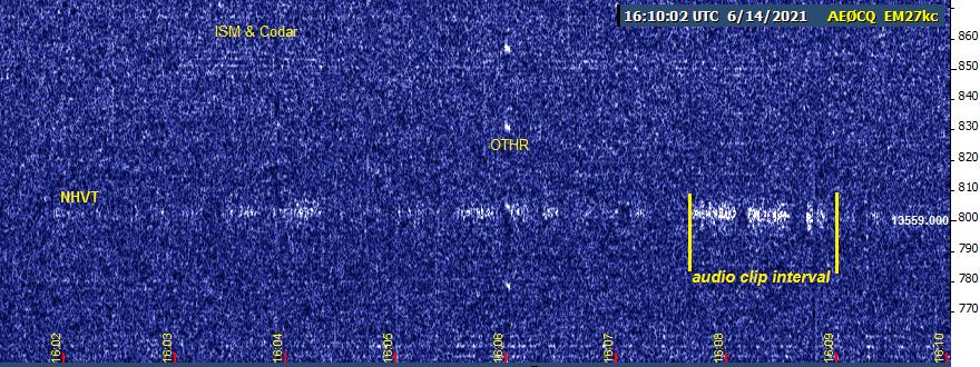
The capture above was from Monday the 14th, and show the signal's trace on Argo from several minutes before the attached audio clip to shortly after audibility was lost.
Most recent reception of NHVY was tonight just after 10:00 PM CDT/0300 UTC, at which time only 7P and K6FRC were coming in strongly, NC and WM were barely perceptible, and nobody else was seen or heard on the band.
---------------------------------------------------------------
![]() File Attachment 1: 14juna06.jpg
File Attachment 1: 14juna06.jpg
![]() File Attachment 2: nhvt2021.mp3
File Attachment 2: nhvt2021.mp3
Re: 22 m Black Cat Hifer
Hi Brian, I am using it. I wired it to use its own built in regulator and I use an old iPhone wall wart. it seems to have good stability and no keying chirp.
Mike ak3f
Re: HiFER Beacon WV
Posted by John Davis on June 19, 2021 at 17:58:49.
In reply to Re: HIFER Beacon wv posted by Michael tyler on June 19, 2021
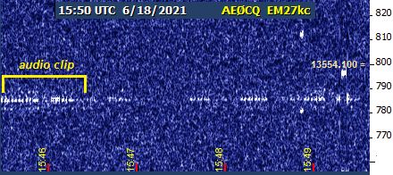
I can now assert definite claim to reception of WV yesterday morning, despite not having positive aural copy in real time.
The Argo trace (above) indicated the signal was near the threshold of audibility at least some of the time, so I made a WAV recording of several minutes length, also using Argo. But even in the absence of Codar or serious sferics, extensive post-filtering with Audacity yielded random results at best, producing little more than imagination alone would have done. A forensic approach would be required.
How I Did It (by Victor Frankenstein). To reanimate the dead signal, I assembled as much a priori information as I could, made deductions, then tested them empirically, making sure I left a path to undo attempts that didn't prove fruitful.
I had a recording that was nearly nine minutes long. I didn't know precisely when it started, but I made it a point to end it exactly at 1538 UTC/10:38:00 AM CDT and logged that fact. I should have had an Argo capture of the entire recording interval, but that file inadvertently came out blank. Fortunately, another capture made a couple of minutes later covered the last two minutes of the recording and slightly beyond.
That was just enough to suggest to me that I needed to concentrate on the interval from 150 seconds to 90 seconds before the end of the recording. But even so, conventional filtering alone was ineffective, yielding only a more or less steady 785 Hz whistle. Therefore, before trimming the clip to its final length, I took advantage of the fact that the 1537 minute started out with a deep fade, and highlighted it as my reference noise sample for Audacity's DSP noise reduction function!
Applying NR made it appear to the eye that I'd wiped out both signal and noise. However, this steady random noise was exactly the sort of thing Audacity's default NR settings were optimized for. When I used moderate equalization to create a reasonable filter half as wide as my radio's 270 Hz filter, and with > 12 dB gain, I no longer had a steady whistle, but definite dots and dashes about 20 seconds into the clip.
Leaving that filter in place, I then experimented with a narrower filter with a Gaussian curve and extracted a bit more signal. I now hear four distinct WVs, and maybe another one or two that's not so distinct. I can't yet discern the entire dits-and-dahs pattern between ID groups, except to say it seems to have been sped up relative to the previous pattern.
Hoping for better propagation again sometime soon.
---------------------------------------------------------------
![]() File Attachment 1: newWVpf.mp3
File Attachment 1: newWVpf.mp3
![]() File Attachment 2: 18juna09.jpg
File Attachment 2: 18juna09.jpg
Re: HiFER Beacon WV
That is so very interesting John. Thanks for working so hard to find and receive the little peanut.....the reports are what makes this fun and thank you for always being there.....mike....."WV" wa8ywo
KAH + ODX
Posted by John, W1TAG on June 20, 2021 at 18:04:13.
Decent short-skip openings this afternoon. Copied ODX on 13566.465 and KAH on 13566.086 kHz around 1755 UTC. QTH Raymond, ME FN43sv. Both signals were CW, copied by ear.
John, W1TAG
EDJ QRV 13555.430 AM 6/21
Posted by WA1EDJ Bob on June 21, 2021 at 01:08:49.
EDJ is back on as of Mon 6/21 AM. Enough WSPRing on 10M for now...
FSKCW3. Hope to have a WSPR machine on too soon.
Heard EH tonight 2030 local. Some "fuzz" observed on the QRSS.
VA3ROM WSPR decoded. Other QRSS but not solid enough to ID.
Bob 13.56 MHz Field Measurement
EDJ
EM83du
Posted by Brian K6STI on June 21, 2021 at 01:18:37.
I've been calculating the maximum input power for various antennas to meet FCC Part 15 rules. Section 15.225 says that maximum field strength for 13.553 to 13.567 MHz should be 15,848 uV at a distance of 30 meters.
15.31 specifies measurement standards. 15.31(f) says:
To the extent practicable, the device under test shall be measured at the distance specified in the appropriate rule section. The distance specified corresponds to the horizontal distance between the measurement antenna and the closest point of the equipment under test, support equipment or interconnecting cables as determined by the boundary defined by an imaginary straight line periphery describing a simple geometric configuration enclosing the system containing the equipment under test. The equipment under test, support equipment and any interconnecting cables shall be included within this boundary.
This suggests that I've been interpreting the 30m distance too conservatively. I've been finding the point in space 30m from the antenna feed point where the field is maximum. This is often well above ground. 15.31(f) says to measure the distance horizontally from the closest point of the equipment under test. The electric field for horizontal antennas decreases greatly as you approach ground. This suggests that much more input power may be legal than previously realized.
Further support is provided by 15.31(d), which say that field strength measurements shall be made, to the extent possible, on an open area test site. It used to say "open field" rather than "open area." There is nothing about making elevated measurements off the ground.
I can't find a specification for height above ground for the measurement. The field from a dipole 30 feet high peaks at a point in space 29m horizontally from the antenna and 17m above ground. If measured 30m horizontally and 1m above ground, the field is about 16 dB lower. At the earth's surface 30m away it is about 20 dB lower. Instead of the 2.4 mW I calculate is legal using the point in space, 240 mW would be legal using the point on the ground.
I'm curious if anyone else has looked into this. Does a near-ground measurement seem reasonable? I'm willing to revise my antenna models and power limits, but it takes a long time because there's so much manual calculation and double-checking involved. I want to do this only one more time.
What distance above ground for the field measurement is reasonable? 0m? 1m? 2m, about the height of a handheld field strength measuring antenna?
Link to current rules (note that it's easy to run into old versions on the web - these are current FCC pages):
https://www.ecfr.gov/cgi-bin/text-idx?SID=7fc9bb3a6f320490a51be4d081753d21&mc=true&node=pt47.1.15&rgn=div5
Brian Re: 13.56 MHz Field Measurement
Posted by Brian K6STI on June 21, 2021 at 05:12:54.
In reply to 13.56 MHz Field Measurement posted by Brian K6STI on June 21, 2021
More from FCC Part 15.31:
(4) Unintentional radiators are to be measured for compliance using the following procedure excluding clauses 4.5.3, 4.6, 6.2.13, 8.2.2, 9, and 13: ANSI C63.4-2014 (incorporated by reference, see �15.38).
The ANSI document costs $192, but I found draft version C63.4rev/D1.05 from 2012 here:
http://www.acil.org/associations/1304/files/C63%204_2012revD1%2005_redline.pdf
Section 8.3.2.1 describes adjusting the measurement antenna height between 1 and 4 meters using both horizontal and vertical polarization to find maximum field strength.
Horizontal antennas will yield maximum field at 4m and verticals at 1m. I propose using these two heights and a 30m horizontal distance.
The horizontal distance is clear for a dipole, inverted V, and two-wire ground-plane because the field is maximum broadside to the plane that contains the wires. For a turnstile, it's not so clear. You could make the case that the distance should be from the closest point of the antenna (a wire end), not the center. After all, that's what the rules say. But the rules envision a compact device that can be put on a turntable on an antenna range and rotated, not a large structure that extends far to the sides and high above. For consistency, I think the antenna center is the right point to measure from. But I could be convinced otherwise. Measuring from the antenna center yields a lower power limit.
With my conservative interpretation of the 30m distance, I calculated that an inverted V with apex 30 feet over ground of average quality could be fed with 3.2 mW maximum. Using the 30m-4m rule, legal power increases to 20.1 mW.
Brian
Re: 13.56 MHz Field Measurement
Posted by Ed Holland on June 21, 2021 at 19:15:54.
In reply to Re: 13.56 MHz Field Measurement posted by Brian K6STI on June 21, 2021
Brian,
Thanks for giving all these factors consideration. It is certainly food for thought.
At such low power levels, even if the allowable input to an antenna had a clear definition, it is not such a straightforward thing to measure in my experience. As an example, 5 mW into a 50 Ohm load would mean 0.5 V RMS. Measurable with a 'scope, perhaps - but we don't all have this equipment.
I still wonder how the 15,848 uV field strength limit was established.
Ed
Re: 13.56 MHz Field Measurement
Posted by Brian K6STI on June 21, 2021 at 20:07:55.
In reply to Re: 13.56 MHz Field Measurement posted by Ed Holland on June 21, 2021
Ed, 15,848 is the strangest number. I've tried scaling it, with square roots or squares, hoping a familiar number pops up. No luck so far. I understand it used to be 10,000 uV/m. That number makes sense.
I just made one last try: 20log(15848/10000). I get 3.999489 = 4 dB. So that's it. Now, why 4 dB?
I've been speaking with Chris of Black Cat. I suggested that on the next version of his little transmitter he add a simple detector. It could just be a Schottky or Germanium diode and a small capacitor. Then all you need to do is measure the DC voltage with a cheap digital multimeter to determine power.
I tried it with a calibrated signal generator. The detector voltage happened to be quite accurate at 1 mW across 50 ohms, but it was off higher or lower. No problem. Just supply a calibration chart. So 2 V DC is 3 mW, 4 V DC is 10 mW, or whatever. There shouldn't be much variation among diodes, at least among Schottky diodes. No calibrated, wideband scope needed. (Your scope bandwidth may need to be at least 50 MHz for good accuracy at 13.56 MHz.)
Brian
Re: 13.56 MHz Field Measurement
Posted by Brian K6STI on June 21, 2021 at 23:05:10.
In reply to Re: 13.56 MHz Field Measurement posted by Brian K6STI on June 21, 2021
I've updated my antenna writeup using the new near-field measurement points: 30m from the antenna centerline, 4m above ground for the horizontal antennas and 1m above for the ground-plane. It will take some time to redo the radiated signal comparison at various wave angles. But you can immediately see that legal power for the ground-plane is much lower than for the horizontal antennas. Unlike them, the ground-plane generates a strong field near ground. The transmit power must be backed off from that of the horizontals to stay legal. I doubt that the ground plane will be dominant below 10� wave angle as before.
http://ham-radio.com/k6sti/hifer.htm
Brian
Re: 13.56 MHz Field Measurement
Posted by John Davis on June 22, 2021 at 06:23:17.
In reply to 13.56 MHz Field Measurement posted by Brian K6STI on June 21, 2021
This is the nightmarish sort of detail I feared and was clumsily trying to deflect with my intentionally vague advice in the earlier, deleted-by-request sub-thread. I perceived that real-world ground effects meant cutting a dipole input back by 6 dB from the calculated 4.7 mW was overly conservative in practice, but now I've got concerns that increasing it by ≥6 dB could be going too far in the opposite direction, and might not be conservative enough to accommodate real-world variations.
I actually started my attempt to clarify the subject from an actual measurement standpoint some time back for a planned article on the subject. There is actually a fair amount of guidance in the published standards, but one needs to be carefully selective.
For instance, the ANSI C63.4-2014 standard cited in §15.31(a)(4) is not the relevant one for our purposes. That's because we are not operating unintentional radiators at 13.56 MHz. Ours are intentional radiators (other than PCS devices) covered under 15.31(a)(3), which specifies C63.10-2013. The 2013 version has actually been replaced by C63.10-2020, which has not yet been referenced by the FCC; but as far as I can tell, there have been no changes in the portions which apply to field strength measurements under 30 MHz.
While the broader scope of ANSI 63.4 allows for either electric or magnetic field measurement of field intensity below 30 MHz, for instance, C63.10 4.3.2 and 6.4.3 specify magnetic measurements with calibrated active or passive loop antennas. Why is this significant? Let's suppose you've decided to run scores of milliwatts into a dipole or other horizontal antenna because you're aware there will be some E-field cancellation at measurement points near the surface. Problem is, if your powerhouse signal ever attracts FCC attention, the radio inspector won't be measuring the partially self-cancelling electric field! He or she will be measuring it as magnetic flux. Caution is recommended.
Other provisions of ANSI C63.10 6.4 specify measurements be made with a rotating turntable for the equipment under test (EUT), or if a turntable is impractical, along 8 or 16 radials under different circumstances, making sure to include the one that produces maximum field strength at the specified distance.
For most transmit antennas, the measurement loop is to be perpendicular to the ground and located 1 meter above it (6.4.6). If the EUT employs a loop, too, additional orientations of the measurement loop may also apply.
Re: 13.56 MHz Field Measurement
Posted by John Davis on June 22, 2021 at 06:50:42.
In reply to Re: 13.56 MHz Field Measurement posted by Brian K6STI on June 21, 2021
You could make the case that the distance should be from the closest point of the antenna .... After all, that's what the rules say. But the rules envision a compact device that can be put on a turntable on an antenna range and rotated, not a large structure that extends far to the sides and high above.
Through incorporation of the ANSI C63.10 standard, the rules actually do accomodate rather large devices, as well as describing the periphery method for defining distance. Test procedures in the standard outline different methods for tabletop, floor-standing, and external-antenna devices under test. Provision 6.4.5 even describes the process for extrapolation for devices with maximum dimension greater than 0.625λ, where the near-field boundary is better described by 2D2/λ rather than the typical λ/2π value.
Re: 13.56 MHz Field Measurement
Posted by Brian K6STI on June 22, 2021 at 10:52:26.
In reply to Re: 13.56 MHz Field Measurement posted by John Davis on June 22, 2021
John, I'm currently using whatever measurement height between 1 and 4 meters yields maximum field strength at 30 meters. I can change that to 1 meter if that's what C63.10 calls for.
Brian
WAS reception
Posted by Steve VA3SC Burlington Ontario on June 22, 2021 at 12:18:22.
June 22...11:45 UTC reception of WAS beacon on 13.566.6 MHz in Burlington, Ontario weak but steady for about 15 minutes. I've logged WAS before. Nice to hear it again. 73 Steve, VA3SC, ODX beacon op.
WA5DJJ HiFER 1 grabber strange
Posted by WA1EDJ Bob on June 22, 2021 at 15:40:20.
I just looked at Dave WA5DJJ's HiFER 1 grabber and there is a strange sig on it.
I'll attach a shot when I find my authentication data.
Best described as a large slow square wave with 20 Hz shift. Sure strange for a ISM sig?
Have a look.
Bob The last French long wave
EDJ
Posted by Mike Terry on June 23, 2021 at 06:18:15.
After Radio France, Europe 1 and RMC stopped their broadcasts on long wave , RTL has been the only broadcaster since 2020 that still uses this frequency range for France. The operators of the channel in Luxembourg are optimistic that they will be able to continue in the foreseeable future.
See article updated 21 June 2021 here:
https://www.radioeins.de/programm/sendungen/medienmagazin/radio_news/beitraege/2020/luxemburg.html
Re: 13.56 MHz Field Measurement
Posted by Brian K6STI on June 23, 2021 at 13:42:35.
In reply to Re: 13.56 MHz Field Measurement posted by John Davis on June 22, 2021
John, if you have access to ANSI C63.10, it would be helpful if you posted the relevant sections.
I've looked at a number of reports from labs that tested 13.56 MHz equipment for compliance with FCC regulations, mostly card readers and near-field chargers. For the 13.56 MHz radiation level measurement, all used a calibrated loop antenna 1 meter high located 3m from the device under test. The lab then derives the electric field from the magnetic field measurement and extrapolates the value to the 30m test distance specified in 15.225. Neither the electric/magnetic conversion nor the extrapolation, both of which use far-field assumptions, are entirely valid at 3m. Evidently C63.10 realizes this. Passages quoted in lab reports allude to future refinement of the procedure, but today it's permitted.
Regulations require test facilities to have a conductive sheet or screen below the test area. For an inverted V 30 feet high, a conductive ground screen lowers the field strength 1m above ground by 4.8 dB compared to the value above real earth of average quality. That would permit correspondingly higher transmit power. But since a 22m experimenter's antenna will be used above real ground, I don't think this test artifact should be taken advantage of.
For an inverted V 30 feet over average ground, the difference between near and far electric field values calculated by NEC-2 at 30m is 0.25 dB. At 3m the difference is 2.9 dB. This gives you an idea about the validity of far-field assumptions.
Brian
WA5DJJ grabber strange signal
Posted by WA1EDJ Bob WA1EDJ on June 23, 2021 at 18:10:13.
This is the strange square wave sig I mentioned in an earlier post. Lets see if I can attach.
Bob Re: 13.56 MHz Field Measurement
EDJ
Posted by Brian K6STI on June 23, 2021 at 18:10:18.
In reply to 13.56 MHz Field Measurement posted by Brian K6STI on June 21, 2021
I've updated my writeup to calculate field strength 1 meter above ground for all four antennas:
http://ham-radio.com/k6sti/hifer.htm
Legal power levels for the horizontal antennas are substantially greater than when I used 4m above ground, which itself yielded power levels greater than for free-space antennas. Please report any errors or oversights. I encourage anyone with NEC to verify the numbers. The writeup gives antenna dimensions, orientation, and ground constants. The field maximum occurs along the X axis (30m out, 1m up). Contact me using the email address at the bottom of the writeup if you have any questions about the models. One caveat: my version of NEC calculates peak near fields. Peak means two things. First, it finds the scalar value of the field vector. This is helpful since you don't have to select horizontal, vertical, or some intermediate polarization. The second meaning is that it calculates the instantaneous peak value. This means you must multiply the reported value by 0.7071 to get RMS, whose squared value corresponds to power. I don't know if all versions of NEC do this. You can find out if yours does by checking the NEC figures against theoretical far-field values as I did.
I expect that many 13.56 MHz experimenters will choose to keep their current power levels. Using substantially higher power would profoundly change the character of the activity. But if my limits are correct, they provide assurance that 4.6 mW into virtually any horizontal antenna and 2.3 mW into any vertical antenna over almost any kind of ground is legal. One exception that comes to mind is a vertically polarized antenna radiating over salt water. Legal power for that case is somewhat lower than 2.3 mW.
Brian
Re: 13.56 MHz Field Measurement
Posted by John Davis on June 23, 2021 at 22:14:07.
In reply to Re: 13.56 MHz Field Measurement posted by Brian K6STI on June 23, 2021
I expect that many 13.56 MHz experimenters will choose to keep their current power levels. .... But if my limits are correct, they provide assurance that 4.6 mW into virtually any horizontal antenna and 2.3 mW into any vertical antenna over almost any kind of ground is legal.
I hope no-one cranks up the volume to 11 just yet! While I agree with the general conclusion stated above, I believe there is an oversight implicit in the reasoning behind the even higher limits. I hinted at it in yesterday's response, and was trying to work up a more detailed logical explanation of it today. Unfortunately, board maintenance followed by car repairs and other real-world interruptions intervened.
Not only would substantially higher power profoundly change the character of the activity, I suspect it could lead to some unpleasant surprises down the road. The clue lies in what I wrote yesterday, and in something Brian observed earlier today: namely, that the magnetic-to-electric field relationship is not an equivalence at 1 meter elevation! If Brian's calculations are correct, and I believe they substantially are, an E-field detector should (and in practice, does) read substantially lower at 1 m elevation than at 4 m due to ground proximity. But a magnetic field detector does not, and it is a magnetic measurement instrument that the FCC inspector will be using if he drops by to check out a signal 20 dB stronger than anything else on the band!
Alas, I must be off now to tend to civic obligations, and will have to leave the board in maintenance mode most of the evening. Sorry for the inconvenience, but I hope the preceding will at least hint at my point for now.
John
Re: 13.56 MHz Field Measurement
Posted by John Davis on June 24, 2021 at 09:58:56.
In reply to Re: 13.56 MHz Field Measurement posted by Brian K6STI on June 21, 2021
I cannot definitively say WHY but I can tell HOW 15,848 became the value. As Brian notes, §15.225 used to specify 10,000 μV/m at 100 feet, later 30 meters; which itself was fairly arbitrary, except that it made a nice round number whether expressed in actual microvolts/meter or as 80 dBμV/m, per the usual way of expressing it on calibrated FIMs.
Then, in the late Nineties, smart cards and chips were developed. The ANSI-affiliated National Council for Information Technology Standardization Technical Committee B10 ("NCITS BlO") submitted a proposed rule change to the FCC in 1998 to allow 2.5 times greater power and a little wider bandwidth emission mask at reduced intensity) outside the previous 13.553-13.567 MHz band edges. This would bring the US standard into line with the requirements then being proposed by the European Telecommunications Standards Institute ("ETSI"). Why a 2.5 power ratio? That's not explicitly stated in the petition, but it does raise the nice round 80 dBμV/m number to s less round but still conveniently even 84 dBμV/m.
The reason I looked up this rulemaking petition was to confirm some math that's relevant to our field measurement discussion.
You see, the CEPT countries and much of the rest of the ITU actually specify field strength for unlicensed devices in dBμA/m, the magnetic field unit, rather than dBμV/m, the electric field unit. The FCC is kind of the odd duck in the global pond in this regard. Sticking with the electric field convention is more practical in some ways from an engineering perspective: the E-field defines the signal's polarization, after all, and it is very convenient to characterize antennas if you have both field intensity and receiver input measured in volts or fractions thereof, instead of mixing units.
Even so, however, the FCC (like the rest of the world) specifies magnetic field measurements for 9 kHz - 30 MHz Part 15 compliance, albeit expressed in electric field units. This tells us right up front that the FCC's EMC measurement procedures (a) are an agreed-upon fiction, but (b) with a good reason behind them.
The fiction part arises from the conversion of the magnetic field readings to electric field units with the ratio Zo=120π≈377 ohms, as if the readings were being made in free space conditions, where such an assumption would be valid. But we know it's not valid close to the surface of the earth, where the reflected electric field is opposite phase to the source wave and partially nulls itself. The magnetic field is less affected, so the impedance of space in the local vicinity is less than 377 ohms, even though the measurement distance is outside the near field. This might be misconstrued as an artifact--nay, a loophole big enough to drive an 18-wheeler through--because the literal E measurement would be so positionally dependent.
Measuring the less-affected magnetic field, but expressing it in electric units as if the normal E to H ratio existed, allows the FCC's constituents to work with the more familiar engineering terms, but to retain the greater consistency of the magnetic instrumentation.
This does result in a certain degree of confusion sometimes about what we're really measuring. The rest of the world skips the confusion by simply specifying the limit at 13.56 MHz as 32.5 dBμA/m (42 μA/m in linear units) at 30 meters from the EUT, with the base of the receiving loop 1 m above the surface. Done, and done. (That strong preference by nearly all administrations for consistency in measuring intentional radiators is why ANSI C63.10 specifies only a limited subset of the measurement options for unintentional radiators then C63.4 includes. There is some flexibility of technique for different types of devices, such as allowing interpolation when emissions are mainly confined to the near-field, for instance, but not in the type of antenna.)
My reason for emphasizing these points?
Bottom line for safety: If we're gong to substitute modeling for actual measurement in attempting to establish rule compliance, as many will have to do, then I believe it's vital to solve for the same parameters that an inspector will be measuring...nominally a maximum of 15848 μV/m, but in reality, a field of ≤ 42 μA/m 1 m above ground, 30 m from the EUT.
Apples for apples, oranges for oranges. Re: 13.56 MHz Field Measurement
Posted by Brian K6STI on June 24, 2021 at 11:44:26.
In reply to Re: 13.56 MHz Field Measurement posted by John Davis on June 23, 2021
1. The FCC has better things to do than chase down feeble signals buried beneath diathermy trash that bother no one.
2. With NEC it's easy to calculate the factor to convert a measured magnetic field to the electric field for any antenna, ground quality, and measurement height.
Brian Re: 13.56 MHz Field Measurement
Posted by Brian K6STI on June 24, 2021 at 12:33:38.
In reply to Re: 13.56 MHz Field Measurement posted by John Davis on June 24, 2021
Experimenters have always substituted modeling for measurement. It's just that the model was for free space, which is inappropriate.
An experimenter is not responsible for inaccuracies in equipment or technique the FCC might use. If an experimenter in fact complies with the field strength regulation, he is in the clear. A claim of noncompliance based on a flawed measurement is indefensible.
Raising the specter of a visit by the FCC is a fantasy. The FCC has no reason to take an interest in a tiny signal that is mostly undetectable and bothers no one. A knock on the door is not something anyone should fear.
Brian
Re: 13.56 MHz Field Measurement
Posted by Ed Holland on June 24, 2021 at 14:43:25.
In reply to Re: 13.56 MHz Field Measurement posted by Brian K6STI on June 24, 2021
Brian,
I suspect the FCC may get bothered if other 13.56 MHz devices -RFID for example- were to suffer interference from unexpected quarters. While I consider that this would be unlikely, it has the potential (pun not intended) to turn the spotlight on the world of beacons, and spoil our little game.
As things stand, and assuming most beacons operate within the spirit of the regulations, the unpredictability of hearing, and being heard, is what attracts many of us to the world of HiFERs. The magic of low power signals covering unlikely distances is compelling. Perhaps we should have an internal QRPpppp contest running 1 mW or less. As things open up with Solar Cycle 25, it seems plausible.
73s,
Ed Re: 13.56 MHz Field Measurement
Posted by Brian K6STI on June 24, 2021 at 15:15:34.
In reply to Re: 13.56 MHz Field Measurement posted by Ed Holland on June 24, 2021
Ed, if you examine the spectrum around 13.56 MHz at many locations using remote receivers, the strongest signals are never experimental beacons. The ever-present band of trash from about 13.558 to 13.562 generated by who knows what always dominates. This power would be the source of any interference, if that were possible. But the signal generated by a device's own transmitter will be many orders of magnitude greater than any signal arriving from afar. I think the probability of a beacon interfering with anything at all is vanishingly small.
I too find the propagation of tiny signals fascinating. It's remarkable how far a few mW can be heard. It would be less remarkable using the couple hundred mW that I calculate is actually legal in some cases. That's why I expect that many experimenters will choose not to take advantage of the full legal limit. There are lots of hams who think it's more fun to see what they can reach using 5 watts rather than the legal limit of 1500. It wouldn't surprise me if many 13.56 MHz experimenters feel the same.
Brian
Re: 13.56 MHz Field Measurement
Posted by John Davis on June 24, 2021 at 18:46:05.
In reply to Re: 13.56 MHz Field Measurement posted by Brian K6STI on June 24, 2021
If an inspector measures the field by the prescribed method, it's not flawed! While the chance of that ever happening is low, it's not zero.
"If an experimenter in fact complies with the field strength regulation, he is in the clear." --true. And if it doesn't, because he chose to rely on a model that employs different assumptions than the official measurement does, he's up that famous creek.
My point is: Why not simply do the right thing from the start and compute the model for what is actually being measured...namely, the magnetic field?
Re: 13.56 MHz Field Measurement
Posted by Brian K6STI on June 24, 2021 at 19:49:09.
In reply to Re: 13.56 MHz Field Measurement posted by John Davis on June 24, 2021
The flaw is using an invalid constant to convert a magnetic field measurement to an electric field value. If someone uses the free-space conversion factor for a measurement near ground, the result is invalid. The error is not the responsibility of the experimenter.
The FCC field strength limit is for the electric field. That limit is what an experimenter must meet. He has no obligation to meet a magnetic field limit that FCC regulations do not specify.
The chance of the sun exploding tomorrow morning is low, but it's not zero. I give that possibility as much attention as I do a visit by the FCC to a 13.56 MHz experimenter.
Brian
Re: 13.56 MHz Field Measurement
Posted by John Davis on June 25, 2021 at 01:35:51.
In reply to Re: 13.56 MHz Field Measurement posted by Brian K6STI on June 24, 2021
The FCC does NOT specify measurement of the electric field! Check it out.
They express the limit in electric field units1; but by incorporating ANSI C63.10-2013 into the rules2, they actually specify measurement of the magnetic field3.
The "invalid constant" is not a flaw. it's the law. The free-space conversion factor is enshrined in the measurement standard itself! It's that way on purpose in the US. (See footnote [24] in reference 3.) If an instrument using a loop calibrated in the standard way is compared to a computed electric field of 15.848 mV/m at 1 m above ground, how do YOU think the physical instrument is going to read?
This matters because over the last couple of weeks you've gone from telling us the old rule of thumb power results would be 6 dB too high, to now saying it's at least twice that many dB too low. This is quite a change, reflecting your evolving understanding of the applicable factors, and thus should be open to review and question. That's how we may all eventually arrive at a better understanding of the issue.
The changing perspective is a bit worrisome, however, when also couched in language that implies nearly anything goes because we're not likely to get caught anyway.
So, why not keep an open mind for a while longer and run your version of NEC again on one of the antenna examples, say, the dipole? If it'll do so, see what the magnetic field would be at 30 m distance and 1 m height for the theoretical power that would give a 15.848 mV/m reading on an electric field instrument at the same location; and/or, try to determine the safe input power for 42 μA/m at that same spot. Re: 13.56 MHz Field Measurement
____________________________________
1 §15.225(a) The field strength of any emissions within the band 13.553-13.567 MHz shall not exceed 15,848 microvolts/meter at 30 meters.
2 §15.31(a)(3)
3 ANSI 63.10
4.3.2 Magnetic field measurements (9 kHz to 30 MHz) "Either passive loop antennas or active loop antennas, as specified in Table 4 and Table 7 and/or CISPR 16-1-4:2019 shall be used to measure magnetic fields in the frequency range of 9 kHz to 30 MHz. See Table 7 for applicable conditions of use of loop antennas.[24]"
Footnote [24]: "For the United States, the regulatory limits below 30 MHz are in terms of μV/m. By convention, magnetic field strength is converted to an electric field strength based on free-space impedance [1 μV/m = (1 / 377 Ω) � 1 μA/m]."
6.4.3 Measuring antenna selection, location, and test distance "Radiated emission tests shall be performed in the frequency range of 9 kHz to 30 MHz, using a calibrated loop antenna as specified in 4.3.2, at a suitable site and measurement distance as specified in 5.3." (followed by extrapolation procedures for situations where the measurement cannot be made at the regulatory specified distance, including inside or outside near-field region)
Posted by Brian K6STI on June 25, 2021 at 14:23:52.
In reply to Re: 13.56 MHz Field Measurement posted by John Davis on June 25, 2021
John, why didn't you post the 63.10 excerpts several days ago when I twice requested them? It would have saved a lot of trouble.
The magnetic loop passages you quote are similar to those in ANSI C63.4, which I have access to. I'm familiar with the ideas. The footnote describes the conversion factor of 377 ohms as "by convention." That convention is not appropriate for fields near ground because it yields an incorrect value. The footnote does not prohibit use of a correct conversion constant, one that yields the true electric field strength.
I'm open to providing a second set of power limits based on magnetic field values with the electric field derived using 377 ohms. This would be for those who fear a visit by the FCC and want to avoid a technical argument about measurement technique. But I'm willing to do this only if I can study C63.10 myself. I want to assure myself that there aren't any additional sections that may be relevant. For example, 4.3.2 refers to Table 7 for "applicable conditions of use of loop antennas." I'd like to see Table 7.
"This matters because over the last couple of weeks you've gone from telling us the old rule of thumb power results would be 6 dB too high, to now saying it's at least twice that many dB too low. This is quite a change, reflecting your evolving understanding of the applicable factors, and thus should be open to review and question. That's how we may all eventually arrive at a better understanding of the issue.
The changing perspective is a bit worrisome, however, when also couched in language that implies nearly anything goes because we're not likely to get caught anyway."
I am happy to have my work reviewed and questioned. I've invited anyone to spot errors or oversights. I revised the power limits as I corrected calculation errors, found more accurate ways to model the antennas, and discovered new parts of the FCC rules. I believe a visit by the FCC to check radiated power is so extremely unlikely that it should worry no one. That does not mean that I believe people should ignore FCC rules. I have never suggested "nearly anything goes."
Send me C63.10 by email.
Brian
P.S. - The formula in the footnote is incorrect, even for free space. It should be 377, not 1/377. Is that in C63.10 or did you add it?
Re: 13.56 MHz Field Measurement
Posted by John Davis on June 25, 2021 at 16:30:25.
In reply to Re: 13.56 MHz Field Measurement posted by Brian K6STI on June 25, 2021
Typing is a slow and painful process now, so it took almost two days since your recent request before I had the free time required to do an accurate job with what I ultimately posted. Even typing this message took so long that I may be driving through bad weather once I finish. (FYI, due to family obligations, I may be unavailable for any further posts til Monday.)
I won't be emailing ANSI C63.10. I agree that you need access to it, but I simply cannot toss into the cloud any document that has my name as the sole licensee watermarked on every single page. I've been looking to see if I could find any place online where you could read a draft copy, similar to what you posted for C63.4, but so far have turned up nothing. Thus, even though it's slow and tedious, for now I'll have to continue referring to applicable provisions and posting relevant excerpts as soon as I can.
Here, for instance is part of the provision that includes Table 7. I believe it's particularly critical at this juncture, because it explicitly requires measurement of the magnetic field and conversion with the free space impedance value. Emphasis in italics in the text below is theirs; in bold is my additional emphasis:
4.3.1.2 Antennas for final compliance measurements
Table 7, Table 8, and Table 9 contains the complete list of antennas that are permitted to be used for making final compliance measurements (including emission maximization measurements) for this standard and identify the frequency ranges over which those antennas are permitted to operate when making final compliance or emission maximization measurements. Only the antenna types specifically listed in Table 7, Table 8, and Table 9 and used in the frequency ranges listed for their operation in Table 7, Table 8, and Table 9 (and used in a manner consistent with the normative footnotes in Table 7, Table 8, and Table 9) shall be used for making emission maximization and final compliance measurements.
Table 7 �Radiated emissions antennas for use in making final compliance
measurements on devices (9 kHz to 30 MHz)
# Antenna types Footnotes
--- ----------------- ---------
3 Passive loop[a]
4 Active loop [a] [b]
[a] When E-field measurements are required to be made, antenna factors shall be
converted to E-field values assuming a free-space impedance of 377 Ω.
[b] The use of an active antenna for final compliance measurements on devices is
permitted ONLY if the active antenna is equipped with an operating saturation indicator
and ONLY if the saturation indicator is monitored during the course of the testing and
that the monitor does not indicate saturation.
Table 8 �Radiated emissions antennas for use in making final compliance
measurements on devices (30 MHz to 1000 MHz) [etc]
Table 9 �Radiated emissions antennas for use in making final compliance
measurements on devices (1 GHz to 40 GHz) [etc]Note that this section contains only "must" and "shall." The real standard is the magnetic measurement, even in the US, even if "by convention" the FCC chooses to express it in electric field units, and it is clear that the "wrong" conversion factor is intentional.I'm about to bump into the message size limit. More in a few minutes.
Re: 13.56 MHz Field Measurement
Posted by Brian K6STI on June 25, 2021 at 16:44:07.
In reply to Re: 13.56 MHz Field Measurement posted by John Davis on June 25, 2021
John, I asked for C63.10 by private email, not by some delivery path in the cloud. I do not intend to share it with anyone.
Brian
Re: 13.56 MHz Field Measurement
Posted by John Davis on June 25, 2021 at 17:12:14.
In reply to Re: 13.56 MHz Field Measurement posted by John Davis on June 25, 2021
(Continuing) Footnote 24 was an exact copy-and-paste, but it is not a conversion formula as such. It expresses the difference in magnitude of the measurement units under free space conditions. It's an (admittedly awkward) way of saying that it takes 377 uV/m to equal one uA/m; thus, conversely, for each uA/m, you'd have to multiply by 377 to get the equivalent value in uV/m. Same thing, just a confusing way of stating it.
I do not mean to imply that you advocate ignoring the rules. Quite the contrary, your work clearly started out as an effort to model numbers that would keep experimenters safe. At this stage, it seems premature to offer any assurances of safety based on calculations whose underlying assumptions are open to question, let alone planting the seed of thought that it might not even matter.
Nor am I trying to scare anyone by mention of FCC inspections, but am merely trying to emphasize that the assumptions we make in calculating rule compliance need to be the same ones used for actual field measurement procedures.
My discomfort with emphasizing the low risk of inspection is that such views have, in the past, been seen as justification by some for an anything-goes approach. Right now, I know of one HiFER whose signal was measured by the specified procedure, while all the rest appear to be within the realm of plausibility based on good-faith efforts. It's not a bad status quo for the moment.
John
Re: 13.56 MHz Field Measurement
Posted by John Davis on June 25, 2021 at 17:25:35.
In reply to Re: 13.56 MHz Field Measurement posted by Brian K6STI on June 25, 2021
I realize that, but ALL email is basically cloud-based these days...not instantly accessible by just anyone, but once it's gone, it's out there and at risk. Nearly all ISPs read your email by algorithms that let the Big Data entities know right away what you're into. Google knows more about us individually than the NSA does! ...and blabs it eagerly to most anyone who comes up with a fee. I realize you're eager to proceed, but I'll have to find some other way to help.
Re: 13.56 MHz Field Measurement
Posted by Brian K6STI on June 25, 2021 at 17:56:48.
In reply to Re: 13.56 MHz Field Measurement posted by John Davis on June 25, 2021
OK, I agree about the 1/377 formula. It is awkwardly put.
I agree that "shall" in [a] below Table 7 mandates use of the incorrect 377 value. You could have saved us so much trouble by posting this excerpt a few days ago when I requested it. Everything else is unconvincing because it is technically wrong.
I'm going to wait until I can see a copy of C63.10. The regulations are so complex and convoluted that I can't be sure I'm doing the calculations correctly unless I can read it all and see everything in context. I think your email privacy concerns are wildly unrealistic. Why would anyone snoop on my email? If you want, encrypt the document, email it to me, and provide the key by some other method.
By the way, the correct conversion factor from magnetic to electric field strength varies with antenna type, ground constants, and measurement height. For a 1 meter measurement height over average ground quality, the correct constant is about half of the 377 value for the dipole and inverted V, somewhat less than 377 for the turnstile, and greater than 377 for the ground-plane.
Brian
Re: 13.56 MHz Field Measurement
Posted by John Davis on June 25, 2021 at 18:43:58.
In reply to Re: 13.56 MHz Field Measurement posted by Brian K6STI on June 25, 2021
The regulations are so complex and convoluted that I can't be sure I'm doing the calculations correctly unless I can read it all and see everything in context.
Agreed, and if I physically could have posted sooner, I would have. As is, I'll have to see what can be done next week. I'm already four hours behind on my departure today.
"Why would anyone snoop on my email?" Greed, mainly. Mentioned losing my wallet in an email. Minutes later, went to amazon.com, and want to guess what I was greeted with a page full of? Many, many examples I could cite. There's no privacy at all anymore, least of all on email.
By the way, the correct conversion factor from magnetic to electric field strength varies with antenna type, ground constants, and measurement height.
I realize that. But the point of requiring magnetic measurements and assuming free-space impedance for conversion is to provide a worst-case specification that can be tested for compliance uniformly. The FCC could have spared us all a lot of headache by explicitly stating the limit as 42 uA/m in the first place, because that's what the wording of the rules and the measurement procedure boils down to.
Back Monday, if the roads don't wash out.
NO LOWER NET Field Day
Posted by Jerry Parker on June 25, 2021 at 20:37:26.
NO LOWER NET Field Day
Thanks everyone, see you next week.
73's
Jerry VLF to MF converter
OWR
Posted by Jack on June 28, 2021 at 12:25:47.
Hello everyone! First time poster here. I use a couple of Softrock Ensemble II SDR's, one covers HF and the other LF. Sadly, however, the LF will only cover down to 230 Khz and I have been pondering options to get lower coverage. I am considering maybe building a VLF to MF converter (10- 500 Khz let's say) that would utilize anything above 2 Mhz on the HF SDR.
My research shows that North Country Radio used to have what looked like a nice converter, but the output would have been right smack dab on a broadcast band station about 2 mi from me (and I'm already having issues with it on the Softrock). It did have a low pass filter though to cut out the broadcast stations in general which made it appealing.
So I ask what is available? On a shoestring budget, prefer making it myself if possible.
Thanks for your responses and time.
Jack
Re: WAS reception
Posted by bill stewart on June 28, 2021 at 12:33:33.
In reply to WAS reception posted by Steve VA3SC Burlington Ontario on June 22, 2021
Tnx for the report Steve....73 de Bill K4JYS
K6FRC and AN2 reception report
Posted by Bill WB8ELK on June 28, 2021 at 14:50:33.
Received K6FRC 6/28/21 at 0545 UTC on 13.565 CW. Received in Alabama EM64oj Re: VLF to MF converter
Received AN2 6/27/21 at 1830 UTC - Bill WB8ELK EM64oj
Posted by Mike N8OOU on June 28, 2021 at 15:43:11.
In reply to VLF to MF converter posted by Jack on June 28, 2021
Jack
I have both versions of the Softrock Ensemble receivers. Let me confirm that my LF version will indeed cover the advertised frequency range down to 180 kHz. I built and used these some years ago, so my memory of the details has faded, but there is an extra divide by 4 in the LF design that has to be accounted for in the setup of the SI570 chips and/or PC software.
I run Linux, and the Quisk SDR software here. I chose to configure the SI570 chips in a way that allows Quisk to control either card with the same driver. That required a modification to the Quisk driver too.
If you want to go below 180kHz then a converter or other radio will be needed. I found that the LF receiver needed an AMBCB filter to remove unwanted images below 500kHz. With that, the Ensemble LF is a great receiver.
Mike N8OOU 73
SW broadcast on 13.570 kHz
Posted by jim vm on June 28, 2021 at 16:33:11.
A shortwave broadcaster has a 10 kHz wide signal on 13.570 kHz making the Hawaii and Utah Kiwi's almost useless for the upper end Hifers!
Re: VLF to MF converter
Posted by John Davis on June 29, 2021 at 05:07:41.
In reply to Re: VLF to MF converter posted by Mike N8OOU on June 28, 2021
Tim Brannon's converter design is stable and robust:
lwca.net/library/articles/wa5md/lfconvtr.htm
100 years ago
Posted by Mike Terry on June 29, 2021 at 09:19:33.
100 years ago this December, voices spoken on one side of the Atlantic shot through the atmosphere and materialised on the other side of the ocean. It was a moment of jubilation for those involved and proof of concept that formalised the possibilities of an emergent zone of signalling and communications called radio. It also helped to bring into focus the unrealised potential of this technology as a mechanism for access to, and transference of, signals of all sorts from around the globe.
These first transatlantic voices were carried on wavelengths of around 200 metres.
An interesting article here: Re: 100 years ago
https://www.thewire.co.uk/in-writing/essays/deep-in-the-dial-lawrence-english-on-the-enduring-appeal-of-shortwave-radio
Posted by John Davis on June 29, 2021 at 17:48:46.
In reply to 100 years ago posted by Mike Terry on June 29, 2021
Mr English waxes a bit more poetical than factual in the article. The first voice across the Atlantic was 115 years ago this December (Brant Rock to Macrihanish) on LF, while the 1921 amateur tests (Greenwich, CT, to Androssan, Scotland) were strictly Morse. The official test station, 1BCG, used a tube CW transmitter, as did 19 other stations copied on December 11, and half a dozen more still used spark transmitters. It also took place on frequencies around 1300 kHz, which isn't exactly shortwave these days. Even back then, shortwaves were considered 200 meters or shorter.
Paul Godley, pictured in the article, was indeed the receiving operator, but not using the loop aerial in the photo. He had met Harold Beverage on the voyage over, and was persuaded to employ a nicely directional wave antenna, more than a quarter mile long. He was operating a superheterodyne receiver, and Edwin Armstrong was present at the sending site in Connecticut.
It took another year for the first UK signals to be copied in the US, and another year after that for the first transatlantic two-way contacts to happen.
Re: SW broadcast on 13.570 kHz
Posted by Ed Holland on June 30, 2021 at 04:07:44.
In reply to SW broadcast on 13.570 kHz posted by jim vm on June 28, 2021
On occasion, I've heard this station - or rather it's sideband splatter. Certainly this year. The language sounded like Mandarin
SAQ Annual Transmission - Sunday 4 July
Posted by Mike Terry on June 30, 2021 at 08:55:32.
The annual transmission event on the Alexanderson Day with the Alexanderson Alternator from 1924 on VLF 17.2 kHz CW with the call sign SAQ, is scheduled for Sunday, July 4th, 2021.
The Alexander Grimeton Association are planning to carry out two broadcasts to the world from the old Alexanderson alternator SAQ. Only required staff will be in place, due to the ongoing pandemic.
Transmission schedule:
1. Startup and tuning at 10:30 CET (08:30 UTC) with a transmission of a message at 11:00 CET (09:00 UTC)
2. Startup and tuning at 13:30 CET (11:30 UTC) with a transmission of a message at 14:00 CET (12:00 UTC)
Live Video from World Heritage Grimeton Radio Station:
Both transmission events can be seen live on our YouTube Channel. The live video starts 5 minutes before the startup and tuning.
More information here:
https://alexander.n.se/alexanderson-day-2021/?lang=en
Re: VLF to MF converter
Posted by Jack on June 30, 2021 at 12:37:36.
In reply to Re: VLF to MF converter posted by Mike N8OOU on June 28, 2021
Hi Mike,
Mine doesn't cover down to 180 Khz. I asked the designer to take a look at he says it won't go any lower (230 Khz) than it is now without introducing instability.
A few months ago, when I was getting back into the SWL hobby, I tried to set up in Linux (my default OS), but was not able to. So, I end up using a Win 7 desktop as host for the two Softrock SDR's, then a RDP link between the Win 7 desktop and my Ubuntu laptop, which I use for control.
I am in the process of building a 7th order band stop Chebyshev filter for AM broadcast right now. Like you, I'm getting too many AM Broadcast images when the Softrock is receiving longwave.
Jack
Re: SW broadcast on 13.570 kHz
Posted by John Davis on June 30, 2021 at 16:46:59.
In reply to Re: SW broadcast on 13.570 kHz posted by Ed Holland on June 30, 2021
Here in the center of the country, it's mainly a problem from 1600 to 1700 UTC, sometimes beginning several minutes earlier.
potrzebie