
Re: FCC Approves 135.7-137.8, 472-479 kHz Bands!
Cool beans! I am going to harass thru e-mails the K2 kit company Elecraft. As soon as they make a K2 kit with the 472-479khz option I'm buying one! Re: Acronym
Lee KE6PCT
Posted by Doug Williams on April 01, 2017 at 12:08:26.
In reply to Re: Acronym posted by John Davis on March 28, 2017
Fun fact: It's not an Acronym unless it can be pronounced as a word. Example: NATO is an acronym because it can be pronounced "nay-to" (long O). NDB isn't really an acronym. How do I know this rather useless information? An old George Carlin skit.
Re: Acronym
Posted by John Davis on April 01, 2017 at 18:12:02.
In reply to Re: Acronym posted by Doug Williams on April 01, 2017
>>> Fun fact: It's not an Acronym unless it can be pronounced as a word.
A-ha! You are correct.
However, this being April 1 and all, I might argue that "NDB" can indeed be pronounced as "endib," the ancient proto-Sanscrit word meaning a prize or treasure of ever-increasing scarcity that is, none the less, pursued by only a few hardy souls. ;)
Now, speaking of April 1, one of the funniest online jokes I've ever seen starts out with the phrase: "The smart yard you never knew you always wanted is here." Go to the www.google.com search page today and click the Introducing Google Gnome link.
WSPR-15?
Posted by Chuck, N1KGY on April 02, 2017 at 11:23:49.
Anyone yet running the new WSPR-15 yet? I downloaded and installed the new WSPR-X package and it has -15 enabled, but giving it a go on 2200m and 630m overnight yielded nothing...
Also, looking folks thoughts on WSPR in general - how many folks prefer WSPR to QRSS, DFCW, etc. or vice versa, and why?
I'm going through the process of deciding what to build and run for the coming season on 2200m and 630m. Up until now I've been an "envious onlooker" when it came to LF/MF so I'm in need of an education, please.
UTC - How? Cost? Recourse?
Posted by Frank Lotito on April 02, 2017 at 11:27:45.
ref: ecfsapi.fcc.gov/file/0329181065646/FCC-17-33A1.pdf
and specifically 47CFR97.303(g)(2) >>bottom of page 60 of the above March 29, 2017 publication<<
I'm sure I missed it in the fine print of the revisions specific to 47CFR97, but:
(1) Exactly how does an amateur contact UTC? I would assume, over the Internet (what's their URL), filling in an online form, and possibly paying a filing fee by Pay-Pal, or what ever?
(2) Does the "30 day clock" mean 30 US Government working days (e.g. excluding weekends, holidays), and that starts as soon as you click SUBMIT the online application?
(3) And the biggie, what if UTC denies your application? Do they have to give a reason, and how does the amateur contest the denial?
Some of these may be moot points - but now is the time to get these questions "officially answered," and not by a Philadelphia curbstone lawyer.
73 Frank Lotito K3DZ / WH2XHA Re: UTC - How? Cost? Recourse?
Posted by John Davis on April 02, 2017 at 14:55:29.
In reply to UTC - How? Cost? Recourse? posted by Frank Lotito on April 02, 2017
All logical questions. As stated earlier in the discussion part of the Report & Order (page 8, ¶20), though, the FCC's Wireless Telecommunications Bureau will be issuing a bulletin outlining the procedures... hopefully, before the effective date of the Rules.
Re: FCC Approves 135.7-137.8, 472-479 kHz Bands!
Posted by Paul on April 02, 2017 at 16:22:55.
In reply to FCC Approves 135.7-137.8, 472-479 kHz Bands! posted by Ed, KI6R on March 31, 2017
And the best part- KPH (and KSM) operations on 500 kc. are still protected from amateur interference. Re: FCC Rulemaking Helps HiFERs Too
Posted by Paul on April 02, 2017 at 16:30:02.
In reply to FCC Rulemaking Helps HiFERs Too posted by John Davis on March 31, 2017
That is wishful thinking. However, the CODAR installation near me has no plans of changing. They are a bunch of hippies who have no idea how the equipment works, and do no maintenance, other than checking to see if the antennas are still vertical. The equipment itself is located in the basement of a historic building that was built by Marconi himself around 1915 for the purposes of housing the Chief Engineer and his family in charge of the giant spark transmitter near San Francisco. The coax cable from the equipment to the antennas is Radio Shack RG-58 ran through some plastic flex conduit and buried a couple inches below the surface. Frankly, I have seen 11m installations done to higher standards.
Re: Acronym
Posted by John Davis on April 02, 2017 at 18:21:31.
In reply to Re: Acronym posted by John Davis on April 01, 2017
In case you missed the Google page on April 1, the Google Gnome video is now at: youtu.be/vNOllWX-2aE
IMO, it's one of their better ones over the years, right up there with Gmail Blue ("we tried brown, but it was a disaster") and the one on how autocompletion works. And of course, our CW fans may remember this one fondly too: www.youtube.com/watch?v=1KhZKNZO8mQ
John
Re: FCC Approves 135.7-137.8, 472-479 kHz Bands!
Posted by Chuck, N1KGY on April 02, 2017 at 18:37:02.
In reply to Re: FCC Approves 135.7-137.8, 472-479 kHz Bands! posted by Paul on April 02, 2017
"...operations on 500 kc. are still protected from amateur interference."
The irony of that fact, and how it has remained "justified" over the course of the last century is so total, and so perfect, that it might be a diamond...
But however it came to be I'm glad that KPH and KSM are still protected.
Re: FCC Rulemaking Helps HiFERs Too
Posted by John Davis on April 02, 2017 at 18:37:16.
In reply to Re: FCC Rulemaking Helps HiFERs Too posted by Paul on April 02, 2017
Paul wrote:
...a bunch of hippies who have no idea how the equipment works, and do no maintenance, other than checking to see if the antennas are still vertical.
Well, that's actually better than some CBers I knew...or even our local short-line railroad, who for the past several years seemed to have no clue why their UHF radios didn't reach very far after a windstorm bent the mounting pole for their repeater's vertical folded-dipole array here in town, so that it was mainly warming the clouds thereafter. ;)
No more Part 5 licenses will be renewed for CODAR once the rules take effect, so if any signals remain in the band beyond 2022, they will hopefully soon receive a friendly but official visit. No more washboard kerchunk-kerchunk signals stomping all over FRC as three of them are doing this afternoon; nor anyone else, if all goes well.
PVC back on
Posted by Ed Holland on April 03, 2017 at 21:48:34.
My apologies to anyone hoping to hear PVC last week.
The usual operator error caught me out again (PVC switched off for a listening session and not switched on again). Alas, I was out for the week, and only was able to restore operation on Friday evening.
Perhaps for this, the opposite of one of those timed light switches - turn the dial and get 20 minutes of radio listening, after which PVC is reactivated?
/Ed
Aluminum Masts for H-Field Antennas?
Posted by A. Green on April 04, 2017 at 21:26:47.
I've been eyeing some USG surplus "portable" antenna mast kits for a pair of H-field receiver delta loops I could stow in my car and setup at remote locations. These use aluminum masts. For example:
http://www.ebay.com/itm/ANTENNA-TRIPOD-29FT-ALUMINUM-PORTABLE-TOWER-MAST-KIT-NEW-/361384099911
On another forum, I was advised against using aluminum masts for reasons that weren't at all clear to me. So I ask the VLF experts: is there a technical reason aluminum is a bad choice for H-field loops?
Thank you for your time!
Class D Audio Amplifier
Posted by Frank Lotito on April 04, 2017 at 22:10:30.
ref: www.MCMelectronics.com and MCM part numbers 50-20805 and 50-20810, and others
I know what a Class D RF amplifier is. But what is a Class D audio amplifier? Some sort of marketing hype, or using "hard on / hard off switching" technology of some sort?
73 Frank K3DZ / WH2XHA
Re: Aluminum Masts for H-Field Antennas?
Posted by John Davis on April 04, 2017 at 22:38:31.
In reply to Aluminum Masts for H-Field Antennas? posted by A. Green on April 04, 2017
I might dispute the term "H-field loop" on general principle, but I can't find any real RF-related reason not to use an aluminum mast for the center support of a delta loop intended for temporary receiving use. You'll presumably be using some sort of insulator(s) to stand off the wire a few inches from the mast; and if you keep the lower corners of the deltas symmetrical with respect to the mast and the earth, the metallic support shouldn't contribute anything to electrostatic pickup.
There might be other materials less susceptible to mechanical damage in the event of high winds, but the main objection I see to the one you cited is its cost. At basically $10/foot, that's kind of painful. Even though I realize the tripod is the largest part of its cost, I suspect MFJ or DX Engineering might be able to offer a less expensive alternative.
Good luck and best DX!
John
Re: Class D Audio Amplifier
Posted by Ed Holland on April 04, 2017 at 22:43:21.
In reply to Class D Audio Amplifier posted by Frank Lotito on April 04, 2017
Hi Frank,
Yes, exactly. Basically a switching "Push Pull" o/p stage is operated at a supersonic frequency. The output goes through a low pass filter. Audio is impressed on the switching stage by variation of the duty cycle between the hi and low parts of the switching. At 50% duty cycle, the mean output is zero etc. etc.
The advantage is that high output power can be achieved without such high dissipation in the output devices as would be seen with linear stages.
www.analog.com/en/analog-dialogue/articles/class-d-audio-amplifiers.html
Hope that helps,
Ed
Re: Class D Audio Amplifier
Posted by John Davis on April 04, 2017 at 23:16:42.
In reply to Class D Audio Amplifier posted by Frank Lotito on April 04, 2017
Class D audio amplifiers are definitely not hype. They've been around in discrete form for over 50 years, and in the last decade or so have kind of taken over the power audio IC market. It's very hard to find an analog power chip of more than a couple of watts these days because of the high efficiency and low heat sinking requirement of the Class D versions. (I mention power ICs specifically, because they're the heart of those amplifiers MCM sells.)
You know that in Class D RF conversion, a pair of transistors--or banks thereof--are continuously switching the output of the amplifier between the + and - rails (or + and ground), 50% of the time at one rail and 50% at the other assuming all is well. The result is an output consisting of a square wave which may be superimposed on a DC level that represents the midpoint between the two rails. You block the DC, if any, and filter selectively for the fundamental frequency of the RF signal.
Working at VLF frequencies of at least twice the maximum audio frequency to be handled, Class D audio is much the same except for two things:
(1. The duty cycle of the switching varies with the applied audio so that the transistor(s) for the + rail are on a higher percentage of the time when the audio is plus-going in polarity (anywhere up to near 100% duty cycle) and the transistors for the - rail are essentially off; while for negative audio polarity, the situation is reversed.
(2. The resulting audio frequency voltage variations on the output line are what is desired in this case, while the RF component is blocked by a low-pass filter.
If you search the Texas Instruments site for datasheets for the part numbers mentioned in the MCM description, you'll probably come across a link to white papers or application notes that go into a lot more detail on their operation.
John
Re: Aluminum Masts for H-Field Antennas?
Posted by A. Green on April 04, 2017 at 23:48:12.
In reply to Re: Aluminum Masts for H-Field Antennas? posted by John Davis on April 04, 2017
Thank you! That's exactly what I needed to know. And, indeed, apologies for the sloppy nomenclature in my closing paragraph. Yes, the price for some of these kits--including the one I linked--is sufficiently steep (x 2), which is why I figured I better get some informed input. As you say, I was pretty sure with a stand-off I should be golden, but I am still overall quite inexperienced and flounder on obvious points.
Unfortunately, costs for aluminum tubing seemed to have soared in recent years--unless I'm overlooking something, similar aluminum or fiberglass tubing in comparable lengths/diameters/thickness from MFJ, DX Engineering, TMastCo, and others aren't that much of a bargain. I considered building my own kits, but kept arriving at the disappointing conclusion that it might end up costing me *more* than buying the prefab kits (notwithstanding time taken for construction). I guess the plus side is that surplus is recycling at its finest, and these kits are supposed to be quite resilient when guyed down--a must out in the steppes of Montana.
In any case, thank you again for your kind input!
Re: WSPR-15?
Posted by Andy - KU4XR on April 05, 2017 at 04:56:39.
In reply to WSPR-15? posted by Chuck, N1KGY on April 02, 2017
Hi Chuck: WSPR-15 has been around for a few years. It never gained popularity. It's quite an overkill for MF, and not too exciting to wait on for decodes at LF either. Matter of fact, WSPR-2 does exceptionally well on LF. WH2XND runs 24/7 in WSPR-2 on 136 Khz from Phoenix, AZ. and punches a signal to the New England areas. He is a High Power station, and should be a good night-time catch. A few years back, I ran a lowFER beacon in the 184 Khz range using WSPR-2 and did quite well with it, getting reception reports out to 800 miles +/-, I was using an old Radio Shack HTX-100 and a homebrew Transverter going into an lm386 1 watt audio amp for the PA. At 1 watt DC Input, I may have been getting 800 mW into the antenna, and heaven only knows what was actually getting into the air. My personal thoughts on what kills WSPR-15 (for me here), is the " all, or not at all " reception required to get a decode. 73, and Good luck - Andy KU4XR
Re: WSPR-15?
Posted by Chuck, N1KGY on April 05, 2017 at 14:55:35.
In reply to Re: WSPR-15? posted by Andy - KU4XR on April 05, 2017
Andy, thanks for your reply, and I guess that explains why I haven't seen but a few references to WSPR-15, also. I remember searching the 180~190KHz range for Lowfers back in the early '90s when I first got into ham and experimental radio. Unfortunately, I never had much any real success - mostly due to the incredibly high noise-levels and inability to deploy anything resembling a real antenna in the barracks/dorm/apartments where I lived in those days. 25 years later, and it's amazing how much the technology, and the radio spectrum have changed in that time. My interests have come full circle as well, back to LF/VLF and how we can use them.
We purchased an RF-quiet home property in eastern NC a few years back, and so with the new allocations, I'm giving LF (and MF) another go. For both LF and MF, the receiver I'll be using is the SDRplay RSP-2 I recently picked up, and for a TX, I have been working on a DDS exciter that can directly encode digital information, so no audio stages in the exciter, just a serialized bitstream.
My original intentions for the exciter are as an experimental platform for digitally encoded speech on the MF/HF ham bands, but that's further down the road. First, I've got to establish the transport, which I'm currently planning/assuming will be IFSK, and get that working with text and files... essentially a version of EXChat that lives in hardware, and is capable of cranking up the speed when conditions permit. So I figure, why not also use the exciter for digital operations on 2200/630m as well. Then all that's left for me to have a complete station are PAs for each band - I already have one built for 136Khz, and I can build essentially another copy of it for 475KHz without too much difficulty.
73, Chuck
Re: FCC Approves 135.7-137.8, 472-479 kHz Bands!
Posted by Ed, KI6R on April 06, 2017 at 15:04:24.
In reply to Re: FCC Approves 135.7-137.8, 472-479 kHz Bands! posted by Lee on April 01, 2017
Even a low power Elecraft VLF transceiver would be great. We are going to want a multi-mode XCVR or TX/RX on the new bands since all modes are authorized. The EIRPs are high enough that I foresee the possibility of SSB nets at prearranged times to chat and trade technical notes on our equipment. Coming up with a multi-mode transceiver for the new bands is not trivial. I've built transverters in the past for 6 and 2-meters that interface with a Tentec Paragon 585/586 HF transceiver. Most Tentec transceivers have low level TX RF out (0dBm)and several I/Os that interface with transverters easily. The Tentec I/Os even interface with relay logic sequencers and external PAs. Another option might be to convert an older tube type TX/RX to single band VLF use. Change the HFO and tuned RF circuits. Perhaps something like a Drake T4XC and R4C. Another challenge is going to be a band-switching antenna tuner that can also be remotely tuned within each of the bands.
Re: FCC Approves 135.7-137.8, 472-479 kHz Bands!
Posted by Chuck, N1KGY on April 06, 2017 at 18:27:28.
In reply to Re: FCC Approves 135.7-137.8, 472-479 kHz Bands! posted by Ed, KI6R on April 06, 2017
Ed,
I'm going to have to protest at the proposition of hacking Drake gear, as I have a growing collection of Drake rigs (TR-3, TR-4C, R4b, T-4x, T-4b, MN-4), but your point is well taken - outboard transverters are not trivial to build (and I would add that there will always be the risk of damaging glitches); and neither is totally refitting an existing HF rig simple or straightforward.
It should be interesting to see who comes forward with a kit rig, either as a standalone transmitter or as a full transceiver, for one or both of the new bands. But I'm not waiting...
Using a DDS chip as the LO for a basic up-converting superhet is about as straight forward as it's going to get. There are numerous frequencies between 3 and 10Mhz where all the necessary components for a good IF strip are readily available, at which point all of our past experience at HF with filters, AGC, noise blanking, & etc. can be applied in standard fashion, and doing the conversion with a TCXO>DDS generated LO frequency will give us the stability needed for digital weak signal work without adding unnecessary complexity;
or, we can use established SDR techniques to mix directly down to a digitized ZeroIF - after which all TRX functionality is implemented wholly in software, again eliminating as much complexity as possible without sacrificing stability or functionality.
Either way, we don't have to re-invent the whole wheel...just the portions which are band-specific.
For myself, I'll be doing a "traditional analog" (except for the DDS) up-converting superhet as my first LF/MF rig, since I have an IF strip (on 4915KHz) which I built for experimental purposes years ago. This IF strip uses just one LO source for both RX and TX, and while that source is currently not uber-stable - currently onboard there's just a 4915KHz crystal, not even oven'ed - but all I have to do to obtain the desired stability is to substitute that crystal with a disciplined frequency source... and I've already bought a handful of high stability 10MHz VTCXO modules - which I'll discipline via GPS - in anticipation of such a need.
I'm already half way done building my first PA for 137KHz - a 600 watt Class D MOSFET deck; and I have a 350 watt linear deck in the works using LAPT 2SA1860 and 2SC4886 bipolars, as well. I ordered the transistors and ferrites for all four PA decks as soon as the 137KHz allocation was published, since the same designs can be readily adapted to 475KHz as well as 137KHz (the LAPT transistors have an Ft of 60Mhz! so they could even be used on the lower HF bands).
So, now it's a race to see how quickly I can finish building ;P
Later, I'll probably try my hand at an SDR approach for a full transceiver - but that I'm going to take my time with (and not be dependent upon the success of), since I'll be breaking new ground [for me anyway].
Re: FCC Approves 135.7-137.8, 472-479 kHz Bands!
Posted by Ed, KI6R on April 08, 2017 at 15:46:50.
In reply to Re: FCC Approves 135.7-137.8, 472-479 kHz Bands! posted by Chuck, N1KGY on April 06, 2017
Yes, converting a Drake or other TX/RX may not be the best approach. I'm going to go with the transverter approach using 3.5-04.0 MHz as the IF.
Re: FCC Approves 135.7-137.8, 472-479 kHz Bands!
Posted by John Davis on April 08, 2017 at 16:03:43.
In reply to Re: FCC Approves 135.7-137.8, 472-479 kHz Bands! posted by Chuck, N1KGY on April 06, 2017
Bearing in mind, Chuck, that phase noise and spectral purity requirements are much more critical in a local oscillator for a weak-signal receiver than for transmitting, what measures do you plan to take with the DDS to minimize phase noise and spurs?
John
EAR in April, and an Unknown
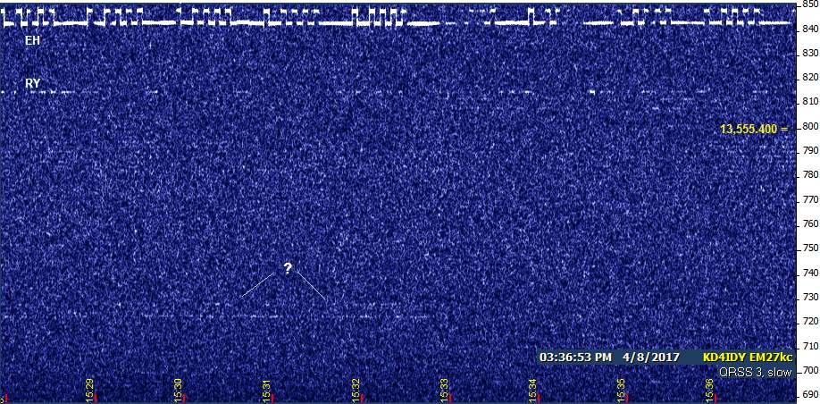
Posted by John Davis on April 08, 2017 at 18:01:30.
I watched SIW WSPR-15 make it through sunset without incident, but then it went into a deep, prolonged fade afterward (as opposed to WH2XND the night before, which had pre-sunset fades then returned to normal after dark), so after 9:15 PM CDT I switched over to watch for EAR, which built up to useful levels during the evening:
This was a welcome change from Thursday night, when I ran Argo on 188.830 the entire night and saw nothing at all! Static last night was running at a median level of S5 with peaks to S9 and sometimes +10. That's around the level where nighttime skywave 1750 m LowFER copy becomes iffy, and is actually a smidgen higher than it was on Thursday night, so signals must not have been very strong the night before.
About 2 AM I returned to the watering hole, where there was a mystery signal showing up intermittently at 185,302.5 while I watched SIW down on 185.185. The mystery signal apparently has a repeating pattern of 1 dash, 2 dashes, 2 dashes, 1, 2, 2, over and over. It first showed up clearly around 3 AM and continued through sunrise, actually becoming clearer after daybreak:

Any ideas?
John
---------------------------------------------------------------
![]() File Attachment 1: EAR07apr.jpg
File Attachment 1: EAR07apr.jpg
![]() File Attachment 2: 07apr-unk.jpg
File Attachment 2: 07apr-unk.jpg
Re: PVC back on
Or, do what I did... Locate the HiFer beacon 70 miles away from your QTH and listen whenever you want. I can hear the HiFer at about S-0.5 to sometimes S-1.
73,
HiFERs Saturday (including END? or ???)
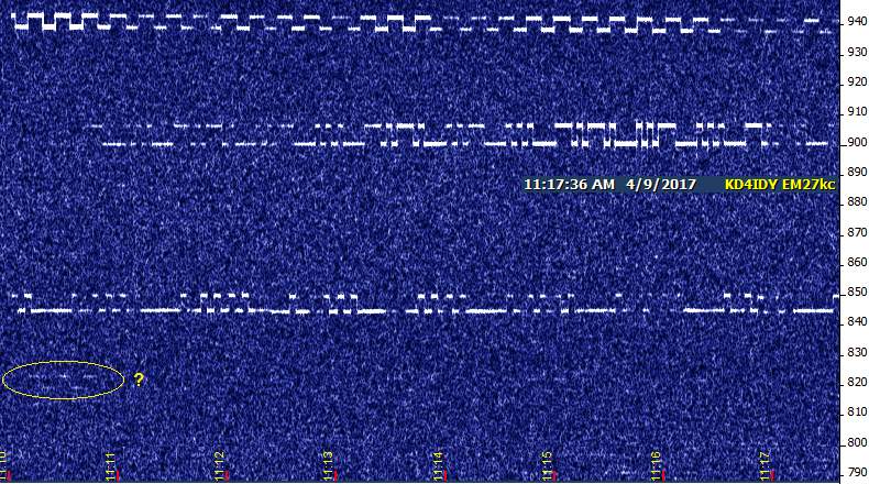
Posted by John Davis on April 09, 2017 at 09:38:48.
Early in the afternoon I saw NC, USC with a good signal, and EH. For short periods, PLM was visible and (barely) audible a couple of times; this was the first time in nearly two weeks that I've seen it, for some reason.
By mid-afternoon, USC and PLM were gone, NC remained, RY was showing up in bits and pieces...and then somebody else halfway materialized down at 13,555.323 kHz. The FSK deviation is similar to that of END, which I saw when it first went on the air last summer, but not since. Back then, it was closer to 13,555.350...and obviously, I can't tell for sure what this one's ID is:
Anyone else seeing someone there? My first thought, because of the spacing, was that I was seeing a 120 Hz sideband of EH, but the keying doesn't line up. So, I'm more inclined to believe it could be END or perhaps someone else who has recently gone to FSK mode.
It lasted only around half an hour, after which NC also became intermittent. An hour later, EH went away too and RY had the floor for a while before also disappearing. By 5 PM CDT, only FRC was around, mainly visible but also sometimes audible between Codar pulses. AZ might have been present, but was thoroughly submerged under Codar.
There are several beacons that have become increasingly scarce here, former regulars which have mostly been absent two months or more. It would be great to have reports from anyone still hearing them. My list of MIA beacons currently includes WV, PBJ, MTI (heard and seen for about 20 seconds roughly six weeks ago), and GNK.
John
---------------------------------------------------------------
![]() File Attachment 1: 08aprb9.jpg
File Attachment 1: 08aprb9.jpg
Re: FCC Approves 135.7-137.8, 472-479 kHz Bands!
That's the challenge in a nutshell, John, isn't it. To approach it in the most conservative way, I should use an analog oscillator PLL'ed to a highly stable [even if noisy] reference such as a DDS, and apply a long enough delay loop in the PLL such that it would produce minimal phase noise in the LO, once locked. That's the theory, anyway.
But I'm not a PLL genius, and I don't see a clear path for a single PLL to cover both bands with satisfactory quality, so at this point I've begun experimenting with a different approach - buffering the output of the DDS, and trimming the level of the buffer to excite a subsequent buffer to just below Class B [between 150 and 175 degrees of conduction] at 2X my desired LO, holding the drive such that it isn't sufficient to pass the noise from the DDS. Then [Class A] buffering that in a High Q stage, then dividing down [to divide out jitter], then through another buffer stage, also Class A with a tuned output for cleanliness, and then one last buffer stage to give me about +12dBm to feed the RX mixer (a homebrew Diode Ring DBM). Using minimal gain in each stage, plus High-Q coupling between stages, looks like it wshould give me a clean enough LO to do a good job...
My existing DBM was't well suited for LF, so I ordered some 1N34As and some FT-50-77cores to build a new DBM and some additional cores for the tuned coupling between buffer stages... I've received them, but haven't built and tested this yet, so it's a work-in-progress.
The buffer stages I'm building will have a Q of ~10-12. The initial results with my existing DBM weren't terrible, which is encouraging, although there will be a lot of work to do optimizing this approach - once built, the new buffer string and DBM should bring me to a decision point on whether this approach is viable or not..
137KHz is narrow enough that the high Q in the LO synthesis chain doesn't pose a problem, and though I've yet to look at how it will do on 475KHz I don't expect it to be a show stopper there, assuming it works well at 135KHz.
Since I'm not well versed in designing PLLs, especially to the stability and nose requirements we're looking at on these bands; then if the "DDS and scrub" method fails I'll probably just build a temp. stabilized VXO as the LO for each band, and go to the races with those, since I've already paid my dibs to the VXO department and know what I can and can't accomplish with one.
Neither approach is guaranteed to work satisfactorily, but I am guaranteed to learn some things along the way ;P Re: EAR in April, and an Unknown
Posted by Gregg on April 10, 2017 at 12:59:30.
In reply to EAR in April, and an Unknown posted by John Davis on April 08, 2017
I've seen this on a few SDR's... Powerline carrier?
Re: EAR in April, and an Unknown
Posted by John Davis on April 10, 2017 at 14:27:55.
In reply to Re: EAR in April, and an Unknown posted by Gregg on April 10, 2017
Gregg wrote:
I've seen this on a few SDR's... Powerline carrier?
Very possibly...especially if you've seen it at frequencies other than 185,302.5 Hz.
There are certainly lots of different kinds of PLCs around the "watering hole," ranging from steady carriers to the six-minute-long Arabic-like squiggles visible just above 185,297, to a recurring stairstep-like pattern that sometimes shows up here. This is my first encounter with one keyed quite like this, though, and seeing that it is at the watering hole, I was kind of hopeful it might be a Part 15 newcomer.
Re: HiFERs Sunday (more ???)
Posted by John Davis on April 10, 2017 at 14:48:04.
In reply to HiFERs Saturday (including END? or ???) posted by John Davis on April 09, 2017
Sunday saw the return of MTI, somewhat more frequent appearances of PLM, better copy of FRC, and snippets of the mystery FSK signal about 13,555.325 kHz. Also, a new snippet of an apparently different FSK signal showed up very briefly at 13,555.417. Any ideas on either of those?
John
---------------------------------------------------------------
![]() File Attachment 1: 09apr04.jpg
File Attachment 1: 09apr04.jpg
Re: HiFERs Sunday (more ???)
Hi John,
This is interesting. I have seen hints of signals that don't quite fit the expected frequency calibration (even allowing for tuning uncertainty). Specifically this is in the vicinity of 13,555.42-ish.
Of late, conditions and/or the chance to listen have not presented themselves. Hopefully more effort on the HiFERs soon.
I've been working more on my '34 Philco project. Currently this is concentrated on an authentic repair of the loudspeaker - recreating the cone and surround based on the fragile remains of the original.
Ed
Re: HiFERs Sunday (more ???)
Posted by Paul on April 11, 2017 at 05:17:24.
In reply to Re: HiFERs Sunday (more ???) posted by Ed Holland on April 10, 2017
Ed,
When it comes to speakers, I find it far better to have them professionally reconed. I use Neal's Speaker Service because he knows the old electrodynamic speakers very well and is affordable. www.nealspeakerservice.com
Ron has repaired and reconed at least 50 speakers for me over the years I have been restoring antique radios. He can even do the deep cone speakers from the high end Zenith consoles.
475Khz homebrewing
Posted by Tweeker on April 11, 2017 at 11:20:24.
I've been thinking a lot about homebrewing lately. I want to build a 630M project. I don't see a good source of 475Khz crystals, but I did come across some 480khz ceramic resonators. I would like to have a go at getting these working in a homebrew transmitter, but I could use a little help working out the theory. Re: 475Khz homebrewing
In theory I would think it should be very similar to the IF of an am radio, But I haven't had much luck finding a circuit to use as a starting point.
Posted by Chuck, N1KGY on April 11, 2017 at 18:02:18.
In reply to 475Khz homebrewing posted by Tweeker on April 11, 2017
I've been pondering a similar problem - many years ago I came by a good quantity of 470KHz crystals in HC6/U cans... was hoping that they'd be in band for the MF allocation when it finally arrived, but such is my luck that I missed by 3KHz ;P
I'd be willing to share them in small quantities for a nominal cost above shipping, if anyone has an interest. Email me at >at.yahoo.dot.com. if interested.
Re: HiFERs Sunday (more ???)
Posted by Ed Holland on April 11, 2017 at 18:29:36.
In reply to Re: HiFERs Sunday (more ???) posted by Paul on April 11, 2017
Paul,
Thanks - I'll check out Neal's and get an idea on what it would cost. This project has already blown through quite a bit of budget, so that is definitely a consideration. Part of me wants the achievement of doing the repair, but along comes risk also! I have repaired speakers before (surrounds on some HiFi woofers) and am generally good at tricky things.
The transformer rewind worked out, and I learned a lot from that. This project has been an amazing adventure so far, with quite a few challenges.
I keep the HiFER monitoring setup running whilst working at the radio bench. It is a good blend of work and play :)
/Ed
Re: 475Khz homebrewing
Posted by Chuck, N1KGY on April 11, 2017 at 19:50:05.
In reply to Re: 475Khz homebrewing posted by Chuck, N1KGY on April 11, 2017
ok, that should have printed as "my.call.at.yahoo.com".
Re: 475Khz homebrewing
Posted by Frank Lotito on April 11, 2017 at 22:18:58.
In reply to 475Khz homebrewing posted by Tweeker on April 11, 2017
As a starting point you may want to get a copy of the RSGB publication "LF Today, a guide to success on 136 and 500 KHz," by G3XDV and M0BMU, ISBN 9781-9050-8636-8. As you become familiar with this book's articles and contributors, you can then start a Google search on what in addition is available for 630 / 600 meters. Lotsa info out there. Don't forget, today you need a 47CFR5 experimental license. Hopefully in the near future, you will only need a 47CFR97 amateur license. (Assuming you are located in the USA.) Have fun - 73 Frank K3DZ / WH2XHA
Re: 475Khz homebrewing
Posted by John Davis on April 11, 2017 at 23:08:15.
In reply to Re: 475Khz homebrewing posted by Frank Lotito on April 11, 2017
Frank's suggestion about the book LF Today is a very good one. It's published by the RSGB, where they've had both bands for years. If you're in the States, unless you just happen to live near a seriously good book store, you may want to go directly to the ARRL shop to order it, as they are the RSGB distributor in the US: www.arrl.org/shop/LF-Today-3rd-Edition/
I just recently ordered a copy myself. Now, ARRL's shipping charge for a book that can go by Media Mail is...to put it mildly...kind of stupid. But the prices for this book on Amazon are heart-stoppingly high! --and they're not even necessarily the latest edition, either. ARRL's is.
Re: 475Khz homebrewing
Posted by JohnG on April 13, 2017 at 05:35:43.
In reply to Re: 475Khz homebrewing posted by John Davis on April 11, 2017
Here is a page from GW3UEP That describes a simple cw TX for 475 kHz
http://www.gw3uep.ukfsn.org/25W_QTX/QTX.htm
73 John/VE7BDQ
Re: 475Khz homebrewing
Posted by Tweeker on April 13, 2017 at 13:02:45.
In reply to Re: 475Khz homebrewing posted by JohnG on April 13, 2017
Thanks, I'll put the book on my reading list, and I'll put that schematic in my file too.
I was hoping to start simple, with a simple oscillator. and work forward from there, adding additional stages. Re: HiFERs Saturday (including END? or ???)
Right now I'm trying to see if I can build an oscillator from the resonators I found. I have read some to the documents from ECS, I think the resonator acts as an inductor when it is resonate. So I think I should try building a colpitts oscillator, I'm still trying to work out what vales to start with, and it will probably take some fiddling to get it to work.
Posted by Paul on April 16, 2017 at 17:41:56.
In reply to HiFERs Saturday (including END? or ???) posted by John Davis on April 09, 2017
Only thing heard this Easter Sunday (besides FRC) is a beacon sending "T T T T T" and nothing else. It is on 13.559.80 as far as I can tell on the R-390A. Also heard on the Kenwood receiver. Comes in best on the 10-20m OCF dipole optimized for N/W-S/E.
Sunday Beacons
Posted by Ed Holland on April 17, 2017 at 22:23:21.
Hi Folks,
Good conditions yesterday, at least at the 13,555.XXX watering hole. NC and USC were there of course with NC moving a lot during the afternoon's session one or other of these sometimes audible as well as clear copy using Spectrum Lab. Also EH, and I thinks what passed as RY from the weak screen traces. I have screenshots but the're on my computer at home.
I wasn't able to hear our friends above 13,562, or AZ at the lower band edge. In fact AZ has been absent from my loggings for a while recently, despite being a consistent copy in the past.
More antique radio rebuilding during the listening saw the first part of cone reconstruction done - pics attached. Also dissection and careful note taking of the O/P transformer
Cheers and 73s
---------------------------------------------------------------
![]() File Attachment 1: post-125875-0-27096000-1492460497.jpg
File Attachment 1: post-125875-0-27096000-1492460497.jpg
![]() File Attachment 2: post-125875-0-34832800-1492460590.jpg
File Attachment 2: post-125875-0-34832800-1492460590.jpg
Re: HiFERs Saturday (including END? or ???)
Hi John,
I was worried about my beacon being MIA too. I put it on a scope Saturday and the RF looks good, and my MFJ259 antenna analyzer shows my antenna is still good, 1.6:1 VSWR.
I put a fresh 12V 7Ah gel cell on too.
Chris Re: FCC Approves 135.7-137.8, 472-479 kHz Bands!
KD4PBJ
PBJ
Posted by Chuck, N1KGY on April 18, 2017 at 02:28:42.
In reply to Re: FCC Approves 135.7-137.8, 472-479 kHz Bands! posted by John Davis on April 08, 2017
John, what are your thoughts on using this DDS/VFO kit for LF & MF?
http://www.qrp-labs.com/vfo.html
If I go this route, it would cut my time to QRV substantially versus having to home-brew something to get on the air. Whatever I then cook up, could liberate the QRP Labs DDS for other purposes... once I've got all the bugs worked out.
Thanks, Chuck
Re: HiFERs Saturday (including END? or ???)
Posted by John Davis on April 18, 2017 at 14:42:10.
In reply to Re: HiFERs Saturday (including END? or ???) posted by Chris Waldrup on April 18, 2017
>>> I was worried about my beacon being MIA too. >>>
Right now, I think most of PBJ's absence at my QTH can be explained by the gradual expansion of the first skip zone caused by continuing low solar flux. Even MTI, which formerly seemed to have a "pipeline" to here, is now highly intermittent. Even NC's pipeline is not all that consistent any more.
With higher sun angles, I am encouraged to see USC more frequently, so perhaps that's an indication others stand a chance once in a while too. And, a G1 magnetic event is anticipated late this afternoon, so perhaps that will be of some temporary benefit, provided I'm out there listening. (I really shouldn't, as this is LOWDOWN deadline week, but it's hard to resist the temptation.)
Hifers Tuesday Afternoon
Posted by John, W1TAG on April 18, 2017 at 22:54:56.
Watching the 22 meter "watering hole" this afternoon, things were very quiet until about 2130Z. For most of the afternoon, only NC and the SIW's were visible. But after 2130, the K3SIW WSPR SNR went from the mid-20s to low teens. By 2230, WM, the SIW's, EH, USC and NC were visible. Tuning up the band, GNK was easy CW copy.
The transition did not coincide with a major solar event. The proton density has been high all afternoon, which is usually the precursor to a coronal hole event (predicted for today). The normal start for a C-H event is for the density to drop quickly, and the solar wind speed to jump. There was a minor drop in density around 2130, and a small increase in wind speed. Not a big deal, and I'm not sure this was related to the prop enhancement.
Interesting, anyway.
John, W1TAG
Re: Hifers Tuesday Afternoon
Posted by John Davis on April 19, 2017 at 03:39:31.
In reply to Hifers Tuesday Afternoon posted by John, W1TAG on April 18, 2017
Excellent report, John. The transition at 2130 UTC was visible here, too...and RY was the herald of the event:
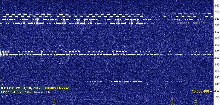
Although it was not a major event, I think X-rays from an M-class flare that began at that time were probably responsible. According to NOAA's animated absorption map, the attenuation at 13-14 MHz was only about 2 dB, but the center of the event was over the West Coast, so the paths we were watching were possibly affected much differently... even significantly enhanced at times over the next few hours. The X-ray curve was also unusually slow to decay.
I'd been hoping to catch the G1 magnetic disturbance that never quite materialized, so I didn't get to see SIW or hear GNK here today. However, solar flux of 80 units was enough of an improvement to let USC show up much more of the day than usual. In fact, it underwent two abrupt enhancements a couple of hours apart. One of those is shown in the 18apr-2.jpg attachment below. During that one, signal level went to S5! The usual level for three normally audible HiFERs at the watering hole, combined, is generally S1 or less.
MTI also made an appearance late in the afternoon, and FRC started being more evident around sunset. No AZ or WV; neither has been seen or heard here in a few weeks now.
I was puzzled by the absence of PLM all afternoon, but when I checked its spot for the umpteenth time half an hour before sunset, there was a keyed signal of some sort about 30 Hz higher than where I normally see PLM. See the attached file 18apr-3.jpg. There were two cycles, or slightly less, per minute; and each cycle lasts longer than the original PLM IDs did. The only one that was strong enough to possibly hear the keying (third from the left) was swamped by a sudden burst of CODAR of equal strength. It does seem that there are up to two dashes embedded within the ID that are somewhat longer than the expected "dah" length.
John D
---------------------------------------------------------------
![]() File Attachment 1: 18apr-3.jpg
File Attachment 1: 18apr-3.jpg
![]() File Attachment 2: 18apr-1.jpg
File Attachment 2: 18apr-1.jpg
![]() File Attachment 3: 18apr-2.jpg
File Attachment 3: 18apr-2.jpg
Measure the EIRP on your short verticle ant using the AA30 analyzer
Here is the web site for the information.
http://njdtechnologies.net/trying-to-figure-out-how-to-measure-the-eirp-of-your-short-vertical-antenna-heres-how/
I was poking around looking for 630 meter homebrew info and found this. I own a AA30 antenna analyzer! Cool beans. Clearly the web site was for 630 meter users, but I am sure the procedure will work for 1750 meter applications. Something to do this off season don't ya know. Differential E-Probe Antenna
Lee KE6PCT
Posted by Frank Lotito on April 20, 2017 at 13:28:18.
On occasion this message board posted discussions on E-Probe antennas. I do not recall discussions on the "Differential" E-Probe antenna design, ref: www.vlf.it/cr/differential_ant.htm . Anyone have Pro / Con comments of the "differential" E-Probe antenna vs the "single ended" E-Probe antenna design? Qualitative or quantitative comments will be appreciated.
73 Frank K3DZ / WH2XHA
PVC on again
Posted by Ed Holland on April 20, 2017 at 20:18:35.
My apologies. PVC inactive until last evening thanks to operator error.
Almost considering hiding it somewhere in the hills nearby with a battery and a panel... out of my reach ;-)
Re: Aluminum Masts for H-Field Antennas?
Posted by A. Green on April 21, 2017 at 03:34:27.
In reply to Re: Aluminum Masts for H-Field Antennas? posted by A. Green on April 04, 2017
After having gotten my hands on one of said surplus kits, I quickly found them rather unwieldy and much less portable than I expected. Shucks. You were right on all counts!
I ended up going for a pair of 12m Spiderbeams:
http://www.spiderbeam.us/product_info.php?info=p3_Spiderbeam%20HD%2012m%20fiberglass%20pole.html
These seem to be sufficiently durable for my loops even with strong winds and are much easier to setup. They are also light in weight and collapse to a small enough size to make international travel feasible--something that did not cross my mind until after they arrived. I wish I'd gotten these sooner.
Re: Aluminum Masts for H-Field Antennas?
Posted by John Davis on April 21, 2017 at 06:23:08.
In reply to Re: Aluminum Masts for H-Field Antennas? posted by A. Green on April 21, 2017
Hadn't heard of Spiderbeams before, but they look pretty impressive. Must be fairly strong, too, as the 40 foot telescoping mast is actually their shortest model.
Re: Differential E-Probe Antenna
Posted by John Davis on April 21, 2017 at 06:35:29.
In reply to Differential E-Probe Antenna posted by Frank Lotito on April 20, 2017
I haven't tried one of these myself, but the principal is sound. It's basically an electrically very short dipole; should have decent directional properties if constructed carefully.
I don't know that I would try to use the TL084 IC all the way to 500 kHz as shown in the article you cited. There are more modern ones that should exhibit much better dynamic range and distortion characteristics at RF. And, of course, such antennas can be built with discrete components. I seem to remember seeing such a design by Dallas Langkford (can't find the link right now, unfortunately) and another one from Eastern Europe several years ago. Perhaps someone will know where to look for one or both of those.
John
Re: Differential E-Probe Antenna
Posted by Gregg on April 21, 2017 at 07:37:11.
In reply to Re: Differential E-Probe Antenna posted by John Davis on April 21, 2017
I would personally use a LT1115 opamp with a discrete jfet input stage... 2SK880 comes to mind.
Cheers!
Re: FCC Approves 135.7-137.8, 472-479 kHz Bands!
Posted by John Davis on April 23, 2017 at 06:39:09.
In reply to Re: FCC Approves 135.7-137.8, 472-479 kHz Bands! posted by Chuck, N1KGY on April 18, 2017
Hi Chuck. Sorry to take so long responding, but it's been a hectic week and I spent some time re-downloading and reviewing some of the literature I'd previously read last year on the Si5351A synthesizer used in the VFO.
Overall, it's not a bad choice. Apparently, if you keep the power supply as pure as the driven snow, you can achieve noise levels close-in to the carrier frequency that are only about 6 dB worse than a typical crystal oscillator. As such, it would not be my first choice for the LO of a zero-IF VLF receiver, for instance. But as an LO for upconverting to your 4915 kHz IF strip, it seems that it might do a very good job!
Do keep us posted on your progress.
John
LF and MF allocations active?
Posted by Chuck, N1KGY on April 24, 2017 at 08:34:34.
Did I miss the publication in the Federal Register? Re: LF and MF allocations active?
Suddenly I'm seeing US Amateur calls on WSPRnet for LF and MF...
Posted by John Davis on April 24, 2017 at 13:46:45.
In reply to LF and MF allocations active? posted by Chuck, N1KGY on April 24, 2017
No, you did not miss publication. That can't happen in this case before the government's Office of Management and Budget gives their approval to the new information collection requirement contained in the proposed Rules (namely, the requirement to coordinate with Utilities Telecom Council).
Not only has that not happened, it hasn't even been 30 days yet since the Report and Order itself was issued!
And not only that, once the Rules are published, then any operator in these bands has to submit their information to UTC and wait 30 days for them to raise an objection.
So, any hams touting their calls on LF and MF Part 97 bands right now are seriously jumping the gun!
Re: LF and MF allocations active?
Posted by John, W1TAGH on April 24, 2017 at 15:38:49.
In reply to Re: LF and MF allocations active? posted by John Davis on April 24, 2017
I've looked back a day or so, and don't see any WSPR reports at 630m that aren't obviously bogus decodes. There are US call signs at LF, but they are coming from reporters who are reporting audio frequencies (1400-1600 Hz) instead of the RF frequency, which is presumably HF.
John, W1TAG
Quiet weekend
Posted by Ed Holland on April 24, 2017 at 21:03:06.
Hi Folks,
In science, we learn that a negative or null result can be just as important as a positive. Well, this weekend was very quiet indeed on 22m. The only signal copied here on the West coast was USC, at around 5 pm local time on Saturday.
I'm considering experiments with a loop aerial, and made a lash-up device for some testing.
Cheers
Ed
Re: LF and MF allocations active?
Posted by Chuck, N1KGY on April 24, 2017 at 21:48:39.
In reply to Re: LF and MF allocations active? posted by John, W1TAGH on April 24, 2017
Thanks John, that's what I thought - still at least two months before our first 'Air Day' on the new bands...
There's a bunch of stations on the west coast, definitely Ham calls, Not Part 5 experimentals that are being reported as spots... there were also a handful of east coast stations reported early this morning, before local sunrise. I didn't check all the To/From particulars, but it seems like too many to be bogus/erroneous reports.
OK, back to the workbench for me...
Re: Quiet weekend
Posted by Chuck, N1KGY on April 24, 2017 at 23:52:32.
In reply to Quiet weekend posted by Ed Holland on April 24, 2017
I'd be very interested to hear your results Ed. I've taken several tries at building a small transmitting loop over the years, and had mixed results.
I can say this -- the sum performance criteria I've learned from my various tests, is that it's all about reducing losses: the variable capacitor has gotta be a butterfly or split-stator cap - I've never had success with any wipers in the RF path; the loop conductor losses are not negligible, even with large diameter CU tubing - "hard" a.k.a. "Red" copper plumbing pipe has a higher resistance per 10' segment than "soft" copper of the same diameter [I assume this is a characteristic of the "hard" alloy]; and all the connections between components are critical, so minimizing the number of joints in the loop is a first design priority, IMHO.
A number of years ago I made an STL with 20 feet of 1" CU "hard" plumbing pipe and a bunch of 45-degree elbows, which "should have been" a killer antenna for 10-40 meters... but the performance was disappointing - it was thoroughly outperformed by a subsequent effort which used a smaller loop - 16 feet of 5/8" CU hardline.
The difference? The second attempt was fabricated with *every* interconnect associated with the main loop and capacitor connections silver-soldered, and there were far fewer interconnects without those 8 plumbing elbows. yes, the elbows of the previous plumbing loop were soldered, but with plumbing solder...which evidently isn't nearly as conductive as the Silver Bearing solder I typically use for RF projects. The loss resistance of the plumbing loop, as fabricated, was nearly an ohm, whereas the total resistance of the hardline loop I still use is well under 1/10th of an ohm. When your radiation resistance is only a handful of mili-ohms, one ohm of loss is the difference between success and failure. My first attempt was a time consuming lesson in the value of every mili-ohm. Live and learn.
The Hardline loop was made with ALL Silver Bearing solder, and uses an HV butterfly capacitor bought from MFJ specifically for the purpose. The hardline STL works great for 40-10 meters - even at QRP power levels, although it's made to handle a hundred watts. I have gotten away with putting it on 75/80 meters by adding an additional fixed capacitor in parallel with the butterfly. And although the efficiency on 80M is only about 5%, it still worked better than "nothing", which was my alternative while living on a military post with no ability to put up a permanent antenna, even a short, end-fed wire.
But I still count myself "lucky" to have built an STL that works well for me - small loops don't model well, and can be incredibly finicky about materials and workmanship, to the point where it seems rather challenging to anticipate the quality of the results until you actually build and test your particular instance of a design.
Good luck with yours!
Chuck
Re: LF and MF allocations active?
Posted by John, W1TAG on April 25, 2017 at 01:56:45.
In reply to Re: LF and MF allocations active? posted by Chuck, N1KGY on April 24, 2017
Chuck,
Just for the heck of it, I picked 15 US amateur call signs from the last few days. All were actually operating on 80-20 meters. The bogus reports are due to the receiving stations not setting up their WSPR software correctly. None of it is real. Heck, I've made these "wrong band" mistakes myself. So, not to worry, it's all legal -- just misguided.
John, W1TAG
WH2XVN, 183.5 kHz copied.
Posted by Ed, KI6R on April 25, 2017 at 03:39:34.
Dave Curry's (WD4PLI)Part-5 beacon, WH2XVN, 183.500kHz from DM04, was easily copied today in Shingle Springs, El Dorado County, CM98 at about 1:00 PM local time. Mike, KI6MTV has built a 6-1/2 foot diameter 13-turn tuned loop that works really well. A one-turn coupling loop is used to connect to the receive. The loop was about 8 feet above ground level and showed a 25dB deep null when turned. Signal strength was about -114dBm into a 75 Ohm load and about 15dB above the noise floor in a 25 Hz I.F. bandwidth. The receiver was an Wandel Goltermann SPM-15 frequency selective level meter which seems to make a superb VLF receiver. Dave has a 30-second pause between his CW ID message which is about one minute in duration. Thanks Dave for putting a nice reference signal on-the-air that we can use to optimize our receiver systems!
Re: LF and MF allocations active?
Posted by John Davis on April 25, 2017 at 05:57:04.
In reply to Re: LF and MF allocations active? posted by John, W1TAG on April 25, 2017
Having gone back in the database over a day myself now, I concur with John A's analysis...just operator error at the reporting end. I'm glad to know "RF Sooners" haven't been a problem yet.
It's been known to happen before, such as after WW II in the days before some of the ham bands were due to be re-opened. The FCC was not amused then; and would probably be even less so now, given how tricky it was to get us these bands in the face of such well funded opposition. Don't want to mess up a good thing.
John D
Lowfer SIW QRT for the summer
Posted by Garry K3SIW on April 25, 2017 at 17:16:02.
Lowfer SIW went QRT for the summer (Sunday). Bob, NK9M needs to tackle the high grass around the antenna! Hopefully it will be QRV around September with a new modulation or two. Meanwhile, thanks to J.B. for keeping EAR going.
73, Garry, K3SIW, EN52ta, Elgin, IL
Re: Quiet weekend
Posted by Ed Holland on April 25, 2017 at 17:36:32.
In reply to Re: Quiet weekend posted by Chuck, N1KGY on April 24, 2017
Thanks Chuck,
Indeed, I've found several good sources that make similar statements about efficiency and construction technique, capacitors, and sources of parasitic impedance.
I may attempt to make a transmitting loop, but perhaps should have been clearer that my first experiment has, and will continue to be for reception. Comparison will be against my standard "random wire dipole" which has proved a very good for reception above 3 Megs or so, and is perfectly acceptable for 80m. This is ~45 ft each leg, with the apex suspended ~20ft into a tree, and the ends at around 6ft above ground. It will be hard to surpass!
Cheers
Ed
Re: LF and MF allocations active?
Posted by Chuck, N1KGY on April 25, 2017 at 17:47:34.
In reply to Re: LF and MF allocations active? posted by John Davis on April 25, 2017
John,
Agreed. 25+ years of lobbying, begging, and repeatedly refuting the specious objections of business interests who would rather spend money to lobby the government instead of putting their own house in order.
"Don't want to mess up a good thing."
My sentiments exactly.
Thanks and 73,
Chuck
Re: Quiet weekend
Posted by Chuck, N1KGY on April 25, 2017 at 20:45:40.
In reply to Re: Quiet weekend posted by Ed Holland on April 25, 2017
Gotcha Ed,
Well there are some rules that apply equally for both TX and RX with small loops, but it seems to me that there are more exceptions than rules in that domain of knowledge and praxis.
There was a group who did some very interesting work on small receiving loops [among numerous other types of specialized antennas and receiver circuits] in the late '80s and early '90s, and documented the research in their newsletter. The group is the Oxford Radio Society, and there were a lot of aviation/aerospace engineers and railroad engineers, and other very smart and creative guys in that club.
Anyway, two thing I recall from their articles on receiving loops -
Te use of fine LITZ wire is the most effective way to increase the surface area/reduce the DC resistance of the wire in an RX-only loop; and that wider spacing of turns [in a multi-turn loop] is better for a given area than more turns because of the higher Q it achieves. The author was pretty clear on the point that even if you had to buy a spool of #32 enameled wire and make the LITZ yourself it was worth the time.
The other item that stands out in my mind - one of them did some experiments with converting the LF/VLF signals up to HF by creating what was essentially a regenerative up-converter that ran in the pickup loop circuit. My memory isn't complete here, but if we could find [a scan of] the paper I'd like to give such a loop a shot, also.
Anyway, as I recall the main antenna loop was resonated on LF/VLF in the normal way, but the smaller/single turn pickup loop is not just the pickup, it's also resonated on/near the HF [IF] frequency, and is operated right at the point of oscillation like an old 'reflex regen' set, - except that the HF frequency is then filtered by an HF crystal prior to being sent to the HF receiver.
The author was specific on the fact that the crystal is acting like a very narrow filter, not as an oscillator component - so I assume that the regen oscillation is serving as an LO, which is occurring at IF-LO=RF, and is not directly on the HF frequency which is being demodulated - so the LO has to be pretty close to the IF frequency, but outside of the HF receiver's detector passband.
This was 30 years ago, and the design was implemented with a tube - I think a 6AC7 - with the crystal and a variable capacitor in series as feedback components [there may have been a potentiometer in that series string, too], but the [pickup] loop and a variable capacitor in parallel serve as the main tank for the "reflex circuit" that does the conversion, while the crystal delivers both regen. feedback *and* the IF output, by a capacitive divider circuit.
The ham who authored the article stated that it gave an effective detection gain of 10~12dB versus the same loop with a "non Q-amplifying design". I'm assuming what he meant was a total gain of 10~12dB in Sig/Sig+Noise because of the gain and very narrow bandwidth effected by the regenerative conversion scheme with the crystal-filtered output.
This design was way ahead of me when I read through it in the early '90s, but I have thought back on it over the years, most recently this winter in contemplating the fact that, with the very narrow bandwidths employed by modern weak-signal modes, such an "antique" converter design might [if implemented with modern components to modern tolerances] might have a real benefit to offer in conjunction with sound-card based SDR methodologies of digging into the noise floor at MF/LF.
Unfortunately this was published/distributed only on paper via snail-mail, having come in the pre-internet 'dark ages', and I have never seen scans of any of those old newsletters available online. I mention it because there is a much higher likelihood that someone here would be interested in such newsletter articles, and might actually have come across some of them and saved them - either on paper or digitally.
If anyone has a copy of this [or others articles from the ORS club], or knows where to find such, I'd be very interested to read through it again and refresh my memory as to the design and the methods employed...
Thanks
Chuck
Oscillator Noise
Posted by Frank Lotito on April 25, 2017 at 21:23:01.
On occasion this column had messages mentioning the need for low phase noise oscillators. These oscillators were for use in transmitters and receivers intended for weak signal transmissions, e.g. one of the QRSS modes or very narrow bandwidth modes such as WSPR or JT9, etc. I am sure the importance of low-noise oscillators applies to equipment for below 500 KHz as well as the HF bands, including the no-license MedFER and HiFER bands.
As I recall, many of the columns' replies simply stated certain oscillator types are far too noisy to be used in equipment for the very slow speed (long dot length) QRSS or narrow bandwidth modes. I did not recall these replies giving quantitative goals for oscillator noise or drift. Can someone give us guidance on which which oscillator designs should be considered for these different modes, and the oscillator / transceiver specifications (phase noise and drift) we should be striving for vs the modes? Maybe what is needed is someone to publish a compendium in this area similar in format to the "LF / MF Antenna Notes" recently published by N6LF (re: http://www.antennasbyn6lf.com?)
Obviously, not all of us pursue the extremes of weak signal transmission and detection. NDB beacon hunters and those dabbling in QRSS3, possibly even WSPR may not need the "state-of-the-art" as those pursuing QRSS300! Many of us use commercial amateur band transceivers in our receiving systems as the tuneable receiving IF, and / or the variable frequency portion for our transmitter's exciter. We may even be using a "modern" transceiver's receiver directly as a "general coverage receiver" for below 500 KHz, Medfer and HiFer applications. I would assume that the transceiver's noise and drift, and other factors contribute to the suitability of our total system for weak signal applications.
The point of diminishing returns may be tempered not only by our interests, but also the man-made and natural RF noise "trouncing" the weak signal sub-bands of interest. We have little or no control over this type of noise. Our recourse is to use the best we can afford w.r.t. noise reduction techniques, be they the electrical circuit design (e.g. high dynamic range / high 3rd order intercept,) where possible directional / noise cancelling antenna systems, and digital signal processing.
73 Frank Lotito K3DZ / WH2XHA
Re: Quiet weekend
Posted by Ed Holland on April 26, 2017 at 19:39:43.
In reply to Re: Quiet weekend posted by Chuck, N1KGY on April 25, 2017
Hi Chuck,
Thank you for the detailed write-up. I will do a little more digging, and some experimentation. I'll post again if anythig interesting turns up.
Even with simple receive antennas, dip meter and noise bridge, I can check Q factor and estimate impedances and losses to explore some of the better construction techniques within my grasp!
Cheers
Ed
Re: Quiet weekend
Posted by Ed Holland on April 28, 2017 at 17:50:21.
In reply to Re: Quiet weekend posted by Ed Holland on April 26, 2017
More receive experiments this weekend...
One issue I can anticipate for a transmitting antenna for a beacon is drift. The best single turn loops quote very high Q factors and commensurately narrow bandwidths. This is fine if one is constantly tuning around the bands, and have implemented a means to tune up. For a single frequency continuous service operation like a beacon, intended to be mostly "Hands Off" any detuning due to thermal drift etc. would be very undesirable.
Of course, given that ISM operation permits only low field strengths, theoretically it would be possible to accept the poor efficiency of a low Q, lossy loop as a trade for more benign tuning characteristics. The difficult issue would be controlling field strength - radiating the equivalent of the ~2 mW into a dipole that we're allowed, and no more.
Food for thought, I suppose!
RY Improved
Posted by John, W1TAG on April 28, 2017 at 23:59:59.
We visited the Maine QTH of Hifer beacon RY today, and after applying a chainsaw to the big tree branch that had downed the antenna, all is well. That antenna is a vertical dipole hung from a tree branch, with the coax heading off at right angles to the cottage. The use of bungee cords at the top of the antenna and the end of the feedline saved things from breaking. Those cords were really stretched out!.
Anyway, hopefully the RY signal will be back to normal.
John, W1TAG
136 kHz. WSPR-2
Posted by John Bruce McCreath on April 29, 2017 at 12:46:50.
I'll be setting up my gear to watch for WSPR-2 activity on 136.000 kHz. dial for the weekend.
73, J.B., VE3EAR
LowFER Beacon "EAR" Re: RY Improved
188.830 kHz. QRSS30
EN93dr
Posted by John Davis on April 29, 2017 at 20:19:44.
In reply to RY Improved posted by John, W1TAG on April 28, 2017
That's great news, JA. It'll be good to have my HiFER frequency reference back on screen more of the day. As soon as the ark settles on dry land once again--if it ever does--I'll head out to the antenna farm and take a look.
Even if I had an HF antenna here in town, it wouldn't be wise to hook up to it today; see attached. The tiny red crosshair is where I am. Fortunately, in the time since that image was valid, a tiny break has occurred in the electrical activity (the first one in nearly 16 hours) that I'm using to make a quick email and message board check. However, radar shows that more is on the way.
John D
---------------------------------------------------------------
![]() File Attachment 1: lightning0429.jpg
File Attachment 1: lightning0429.jpg
Re: Quiet weekend
Had a bit of fun making a lashed up loop, just to get an taster on receive.
I made a PVC cross frame for a loop approximately 12 feet in perimeter, 20 awg insulated wire. Classic arrangement witht the variable capacitor at the top, and an inductive coupling loop connected to a coax feeder at the bottom. The loop is abou 10" diameter, 12 awg.
Tuning is from about 5 Megs to about 15, with a 15 - 140 pf generic capacitor.
Sensitivity is very good considering the effort. It is hard at the moment to site it outside and give a fair chance, e.g. on weak HiFERs but compared to my receive dipole, it is tempting to say they are close.
More experiments to follow.
potrzebie