Re: Oscillator Noise
Let's tackle oscillator noise and drift issues separately. Drift is equally relevant to transmission and reception, but generally noise is a greater concern in receivers. For now, let's stick to noise.
Signal purity in a transmitter is mainly about coexisting with other signals of comparable power levels; but reception is more critical because the desired signals are going to be very feeble at any significant DX. Noise sidebands of the RX local oscillator, and spurious products produced in the oscillator or elsewhere, can be serious. To understand these effects better, I recommend getting hold of a copy of Communications Receivers by Ulrich Rohde, ideally one of the earlier editions that had more emphasis on analog circuitry. (Not everything worth knowing is online.)
Meantime, to give a basic answer about quantifying receiver L.O. noise, I'd refer you to the receiver tests that John Reed KA5QEP has been publishing for several years in The LOWDOWN. In each, he evaluates the sensitivity of a receiver from 500 kHz all the way down as close to 0 Hz as it will tune by applying signals of known frequency and power, and recording the input level at which the audio coming out of the receiver is 10 dB above noise. This also lets him measure the receiver's internal spurs with good accuracy.
What John's results indicate, taken together, is that most receivers deemed good for serious DX at LF have sensitivities of -130 dBm or better at the frequency of interest, and as few spurious responses as possible. The long-popular R-75 has sensitivity in that ballpark at 175 kHz, but it falls off rapidly below 100 kHz and there are many spurs, some of which can be as bad as -80 dBm around 30 kHz. It's considered a good radio for 1750 meter work, NDBs, and 630 meters, though, and has done a fair job for me at 2200 meters as well. My Kenwood R-5000 has its share of spurs in mid-LF, but is a distinctly better performer from 2200 m on down to 30 kHz than the R-75, where the Kenwood's sensitivity remains around -130 dBm.
Contrast that with the R-75 or any other decent HF receiver using an AMRAD upconverter, where sensitivity runs nearer -140 dBm over most of LF, and better than -130 dBm down to 20 kHz with only a couple of spurs of about -120 dBm. Fancy Racal mil/commercial receivers from a couple decades back typically do -130 dBm across LF albeit with fewer spurs. The WinRadio Excalibur Pro hovers around -140 and sometimes near -150 dBm at LF, falls to -130 about 25 Hz, then deteriorates rapidly to -108 dBm around 10 kHz. John Reed will be reporting in an upcoming issue on the HEROS Technology upconverter that performs at -140 dBm or better from 500 kHz down to 10 kHz, becoming a "mere" -130 dBm at 2 kHz!
Is that kind of sensitivity overkill at LF, where noise is often a lot stronger? Sometimes, yes. But I assure you...it's not overkill on quiet winter days! Under such conditions, you still want as quiet a receiver as you can get, capable of rendering a -130 dBm or lower signal. Many "general coverage" radios and transceivers are a lot cruddier than that below 500 kHz, and as a result--no great surprise--they simply don't hear as many signals.
So, let's say for approximation that you want to build an LF receiver or upconverter with sufficiently low noise to receive signals of -130 dBm all the way down to 10 kHz with at least 10 dB S/N ratio. Assuming the gain budget and noise figures of the subsequent receiver stages magically do not deteriorate the SNR existing at the output of the mixer, then how pure does the oscillator have to be?
Assume the mixer requires an injection level of +13 dBm. For the -130 dBm incoming signal to be 10 dB above noise at the output of the radio, the L.O. sideband 10 kHz from the carrier must be lower than -140 dBm. Referencing that to the oscillator carrier, the way oscillator noise performance is generally characterized: (-140 dBm) - (13 dBm) = -153 dBc at 10 kHz. That can be achieved by amateur constructors, but it's not a trivial task. (Commercial low noise oscillators are widely available that can do -160 dBc at 10 kHz, and Wenzel Associates has some ultra-low noise models that push -180.) That close-in noise is not only a function of the radio's master oscillator, but also the PLLs or DDSes that constitute the variable L.O. (plenty of bits in the DAC are crucial in a DDS; 12 or 16 are fine for a transmitter but nowhere near enough for a receiver), and any MMICs or other devices that amplify the signal enroute to the mixer (1/f noise in those will add to unwanted close-in sidebands).
So maybe you don't want to tune down that low? If not, that eases the task, because the noise sidebands continue to fall off with additional separation from the carrier, eventually reaching some final noise floor (plus the occasional higher spur). The same math applies. If you want 10 dB S/N ratio for a -130 dBm input at 137 kHz, then the total oscillator/PLL/DDS noise at 137 kHz from the LO frequency must be better than -153 dBc. This is do-able with attention to oscillator design (crystal type, drive power, etc; see the Rohde book and tutorials at wenzel.com) and careful noise suppression in the power supply line.
Don't expect a bargain-basement crystal in a typical CMOS inverter arrangement fed from a wall wart to be clean enough for truly serious reception, although it may do in a pinch; and don't even think about Epson programmable oscillator modules. They're OK for non-critical QRSS and slow FSK transmission, but apart from their incessant thermal wandering, see Lyle Koehler's Epson article to understand why they would be bad spectrum neighbors in most any band at greater than Part 15 power levels.
More about drift later.
John ID change for AA0RQ Hifer
Posted by Bill Hensel on May 01, 2017 at 15:28:08.
The AA0RQ hifer ID has been changed to PCO which stands for Pine Colorado.
Re: ID change for AA0RQ Hifer
Posted by Ed Holland on May 01, 2017 at 18:48:04.
In reply to ID change for AA0RQ Hifer posted by Bill Hensel on May 01, 2017
Thanks Bill,
I'll listen out. Conditions have been a bit rubbish of late, with nothing to report from the HiFER stations closer to CA. However, one just never knows when conditions might lift, so we keep going!
Cheers
Ed
Re: ID change for AA0RQ Hifer
Posted by John Davis on May 03, 2017 at 04:14:43.
In reply to Re: ID change for AA0RQ Hifer posted by Ed Holland on May 01, 2017
Slight chance I may have seen the new keying sideband pattern of PCO this afternoon about 3 PM CDT at 13,563.550. There was an unexpected but brief opening to Illinois, so when it began to fade I thought I'd check for other rare first-skip-zone problem signals. First I caught a glimpse of MTI which had been missing for some time, but not at audible levels. Then I tuned on up and caught about 5 repeats of a keyed signal that each lasted less than half the time of each AAØRQ cycle the last time I saw it. Without aural copy I can't be certain, of course, but it gives me hope to keep trying as the sun angle gets higher this season.
John
Rarer Than Hens' Teeth
Posted by John Davis on May 03, 2017 at 05:13:33.
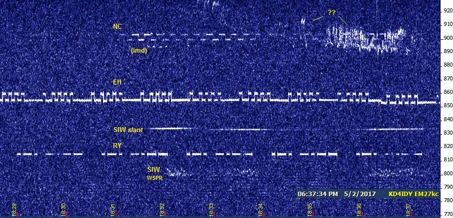
Had one opening to Illinois in progress when I arrived in the field around 2:30 PM today. It didn't last long, but another showed up around 5 PM and continued off and on for about two more hours.
This time, MTI appeared for a little while and was audible for a few minutes, too. No sign of WV, PBJ, PLM, PCO, or FRC this time, however. The SIW duo were not terribly consistent, but I did see this from the slant mode signal:
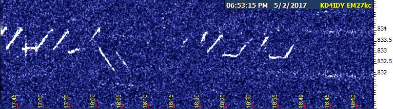
And the WSPR signal, though subject to bouts of QSB, did produce a few decodes:
2244 -25 -1.4   0.137507  0 K3SIW EN52 7
2248 -28 -1.3   0.137507  0 K3SIW EN52 7
2252 -28 -1.1   0.137507  0 K3SIW EN52 7
Maybe the next few months will prove worthwhile at HF after all.
John
---------------------------------------------------------------
![]() File Attachment 1: 02may-wh.jpg
File Attachment 1: 02may-wh.jpg
![]() File Attachment 2: 02may-siw.jpg
File Attachment 2: 02may-siw.jpg
Re: RY Improved
Yup, a definite improvement in RY upon resumption of monitoring in SE Kansas today. See the post titled "Rarer Than Hens' Teeth" for a sample. It wasn't that strong the entire afternoon, of course, but was clearly visible a lot higher percentage of time this afternoon than it had been over recent months. Congratulations, JA.
John D
Paralleled Wires for Antennas
Posted by Frank Lotito on May 03, 2017 at 23:03:54.
A question about paralleling two conductors to use an antenna mast guy wire as a dipole (or as part of another type of wire antenna) - For example, using a stranded stainless steel guy wire with appropriate insulators and cable clamps to construct a sloping dipole. If the stainless wire is paralleled with a stranded or solid conductor copper wire will the resulting dipole antenna have less loss than using just the stainless steel guy wire as the dipole (or as part of another type of wire antenna?) If yes, how much less, e.g. was it really worth the effort to parallel the 2 different wires? I would think that at LF and MF application (where the guy is part of some type of wire antenna) its "six in one, half a dozen in the other." Maybe not so for HiFER (22 meter) application where the guy can definitely accommodate a full size dipole or possibly even an extended center fed zepp... ?
Could the paralleled wire approach have application where a "small in comparison to wavelength triangular shaped one-turn loop antenna" is constructed for VLF / LF / MF by using 2 guy wires. Since small loops are quite inefficient (their radiation resistance is far smaller than their RF resistive loss), could the paralleled stainless / copper wire approach be used as a means to improve VLF / LF / MF loop antenna efficiency?
73 Frank K3DZ / WH2XHA Re: Paralleled Wires for Antennas
Posted by Frank Lotito K3DZ / WH2XHA on May 03, 2017 at 23:13:43.
In reply to Paralleled Wires for Antennas posted by Frank Lotito on May 03, 2017
Oh, let me qualify, when I said parallel wires I meant the two wires are in intimate contact, maybe by clamping them together every few feet, or using a spiral pitch of a few feet where the copper is spiraled around the stainless steel guy cable. And I don't mean "copperweld."
Re: Paralleled Wires for Antennas
Posted by John Davis on May 04, 2017 at 07:30:30.
In reply to Re: Paralleled Wires for Antennas posted by Frank Lotito K3DZ / WH2XHA on May 03, 2017
If the stainless wire is paralleled with a stranded or solid conductor copper wire will the resulting dipole antenna have less loss than using just the stainless steel guy wire as the dipole
Yes, but it will still be lossier than the copper wire alone. How much worse depends in large part on the type of stainless steel.
Ordinary mild steel has a resistivity nearly 10 times that of copper, and stainless steels are approximately four times worse than that. But the big variable in stainless is the RF skin effect depth. Skin depth is proportional to resistivity and inversely proportional to both frequency and permeability...and it is the latter which varies hugely between types of stainless steel.
Stainless can be classed as ferritic, meaning that its crystal structure at the time of manufacture makes it highly magnetic (μ > 120 or so); or austenitic, which exhibits no attraction from a magnet (μ = 1); or martensitic, which may start out with austenitic traits, but due to its alloy composition can acquire magnetic properties from alterations to its crystal structure if worked or annealed. If the cable is stainless 316, for instance, it will start out non-magnetic (μ = 1) and remain that way during use, and will therefore exhibit something near maximum skin depth for stainless alloys. Greater skin depth is especially important for controlling RF resistance effects if the conductor has relatively high resistivity to begin with.
Even though you're wanting the copper to carry the bulk of the RF current, the fact that it's in close proximity to the steel cable means there will be close coupling and a significant current induced within the cable. The power lost in those induced currents, in effect, makes the copper conductor look more resistive at RF. And that's not even mentioning the detuning of the dipole if the steel is magnetic in nature.
The first thing to do if you don't know the type of stainless steel in the cable would be to test it with a strong magnet. If there's any attraction at all, I'd suggest looking for alternative ways of mounting the sloping dipole away from the guys. Or, maybe replace the relevant portion of the top guy wires with a more sympatico material--copperclad steel or annealed aluminum, possibly, and let that be your antenna material (unless a mast is carrying a high wind load structure at the top, the uppermost guy wire doesn't usually have to be as strong as the lower levels); or else a non-conductive guy rope to which you could attach the copper antenna wire. Re: Paralleled Wires for Antennas
Posted by Chuck, N1KGY on May 04, 2017 at 10:47:04.
In reply to Re: Paralleled Wires for Antennas posted by John Davis on May 04, 2017
John,
That post by itself is worth 5 credits for Continuing Education: Engineering: Materials: Metallurgy. Many thanks, sir ;P
On another topic, I'm going to be doing some experiments this weekend with a few configurations of small loops, individually and in array. I've already made up the transformers, and bought a box of RG6 [and the good crimp-on F connectors]...
Re: Current VLF stations?
Posted by Chuck, N1KGY on May 05, 2017 at 01:49:08.
In reply to Re: Current VLF stations? posted by John Davis on March 11, 2017
So I've started doing my loop antenna experiments this evening, and I'm seeing a strong signal on 15.003Khz [give or take a hertz] that I've never seen before. There is no preamp between the antenna and SDR front end, and I don't have the internal amp active, either, so it shouldn't be IMD. And YES, I moved the LO to check if it's an artifact of the ADC ;P
It's definitely not the Alpha on 14.900, although that hasn't been visible to me recently. this sig. is pretty strong, peaking at about 96dBm, with the noise floor running 106 to 103dBm according to the SDR, and it's been clearly audible continuously over the last 10 minutes as I'm listening, occasionally rising another 10 or 20dB above the noise for brief periods, so I'll dare to say it's not local.
For reference, I'm copying the Alpha on 21.100 at just about 100dBm, but not NPM or NLF, which is unusual. Nothing else visible, let alone audible in the 11 to 30Khz zone so far, although further up JJY and WWVB are definitely visible, and FUE (62.2) and MKL (81.0) are just tickling the waterfall, also.
Re: Paralleled Wires for Antennas
Posted by Paul on May 05, 2017 at 05:13:48.
In reply to Re: Paralleled Wires for Antennas posted by John Davis on May 04, 2017
Wow, what a great answer. Thanks, John.
I remember studying that in school while on my way to an EE degree. I do remember that putting dissimilar conductors in parallel really only changed the velocity factor of the otherwise more conductive of the two wires. I forgot about the current distribution and magnetic properties.
With all that said, I rebuilt all but one of my many dipole antennas with bare stranded stainless aircraft cable instead of copper wire. Did it change anything? Nope. Well, it did change that fact that the dipoles don't stretch anymore in really high winds. It also changed the aesthetics since the XYL can barely see the thin aircraft cable against a blue sky.
I remember a commercial OCF antenna I erected between two free-standing towers in the south end of the antenna field that was made from coated insulated solid copper wire of fairly large diameter. The well known antenna maker swears by this wire. I noticed the antenna's resonant frequencies on each band getting lower and lower as winter went on. By the end of winter, the resonant center points were below each of the ham bands! I rebuilt that one with stainless aircraft cable and it is rock solid now. Works about the same as before, only with SWR dips in the middle of the ham bands that stay put.
Stainless Antenna Wire / EZNEC
Posted by Frank Lotito on May 06, 2017 at 11:09:02.
In a recent posting I asked about using stainless steel antenna mast guy wires as part of the radiating system. Thank you for the replies including the direct e-mails to me. I decided to use EZNEC 6.0 to model a few comparative examples. These models might give me a little more insight whether or not a more exotic guy wire material / construction would be necessary.
To start, I will model simple antennas using two different materials, such as the antenna using only 18-8 stainless, or only copper.
EZNEC 6.0 gives the user the opportunity to select a few different antenna materials, but not stainless. EZNEC 5.0 has a little longer list of wire materials, but not stainless. However, the user can input his choice of wire material by inputting two units of measure for that material:
1 - Resistivity in ohm-meter
2 - Relative permeability, reference copper = 1. (All the EZNEC materials 5 & 6 choices have a permeability of 1, but none of the materials are alloys of iron.)
Can someone suggest an online source for the two above units of measure for materials such as stainless 18-8, 316, 302 ? And, for the $64 question, does the magnitude of these these units vary with frequency? I would think the permeability of iron bearing alloys does. The frequencies of interest (in round numbers) are 0.500 MHz, 50 MHz and 150 MHz.
Thank you and 73 Frank K3DZ / WH2XHA
Re: Stainless Antenna Wire / EZNEC
Posted by John Davis on May 06, 2017 at 17:56:28.
In reply to Stainless Antenna Wire / EZNEC posted by Frank Lotito on May 06, 2017
There are a LOT of online resources of this sort, but you'll need to Google a bunch and pick and choose for specific alloys of interest, because I haven't yet found one that covers them all.* You can use the numbers below as a guide, though. They're close enough for NEC calculations, although you may have to convert the resistivity if NEC asks for ohm-meters. Also be aware that I'm giving permeability as μr, the unitless permeability relative to vacuum.
All stainless steels have a resistivity in the 55-90 μΩ-cm range, and nearly all austenitic versions are between 70 and 80, so it's safe to assume a value of 75 μΩ-cm. You'll want to double-check my math, but I think that translates to 7.50E-07 in ohm-meters.
That resistivity is measured at 20 °C. It rises with temperature, and the steepness of the curve depends on the alloy. And, that's at DC. Measuring "resistivity" at RF is meaningless because of skin effect. Skin depth and its resultant effects on apparent RF resistance are what you're using resistivity and permeability to calculate.
As for permeability, it's never exactly 1.0 in even the best austenitic stainless steels. As I recall, it is approximately 1.005 for both stainless 316 or 305-2, even after cold working. Those are the two with the most stable magnetic properties.
The British steel industry considers a steel non-magnetic if μr≤1.3, which covers most austenitic steels before working...but some exceed that considerably after annealing or cold working (including being stretched while in use). Grade 304 can easily rise to μ≥3 after such treatment, grade 302 can give μ≥4, and 301 can reach 6 or 7, depending on the source. Even though non-austenitic steels run a lot higher, anywhere from 100 to maybe 900, you still don't want it any greater than 1 if you can help it because that reduces skin depth and thereby increases effective RF resistance.
(BTW, 18-8 is not a specific grade in its own right, but according to Lawson Products, is a family that includes grades 302, 303, and 304. These are called commodity grades by US manufacturers. They include chromium but not nickel, so they are less effective at resisting magnetization.)
As for the effect of frequency on permeability values, it is largely irrelevant when μr is close to 1. For ferritic and martensitic stainless steels, however, they are obviously going to behave more like ferrite cores, whose properties do vary with frequency, as we well know.
John
(* Not entirely true. ASM International publishes a number of references, at least one of which relates to this discussion. You can get the table of contents online, but apparently you have to buy the book.)
Adding to my EAR collection.
Posted by John Davis on May 06, 2017 at 18:23:32.
Nothing bizarre, there...I just decided I'd try to document reception of EAR in every month of the calendar year. Attached are three samples from last night's reception.
Image 0004 shows the first readable ID of the evening starting to come in around 9:30 PM CDT, finally overcoming the fairly heavy QRN from the Rockies and the Atlantic seaboard.
Image 0008 shows the start of a 70 minute gap in reception after midnight. Whether this was due to a genuine signal fade of that length or a temporary increase in QRN, I could not tell you. I was not conscious at the time.
Image 0018 depicts the final reception of the night, ending 70 minutes before the pleasantly QRN-free sunrise (I was awake again by then); after which even the PLC carriers switched over to daytime conditions.
John
---------------------------------------------------------------
![]() File Attachment 1: 05mayd0018.jpg
File Attachment 1: 05mayd0018.jpg
![]() File Attachment 2: 05mayd0004.jpg
File Attachment 2: 05mayd0004.jpg
![]() File Attachment 3: 05mayd0008.jpg
File Attachment 3: 05mayd0008.jpg
Re: Adding to my EAR collection.
Thanks for the report and screen shots, John. It's nice to know that EAR is still being seen as our season closes.
73, J.B., VE3EAR Re: Rarer Than Hens' Teeth
Posted by John Davis on May 07, 2017 at 21:05:38.
In reply to Rarer Than Hens' Teeth posted by John Davis on May 03, 2017
P.S. - The SIW WSPR decodes show an erroneous frequency. My last use of WSPR-2 was monitoring of XND on 2200 m, and I forgot to reset the "dial frequency" for 22 meters!
Fri & Sat - More Hens' Teeth
Posted by John Davis on May 07, 2017 at 21:06:50.
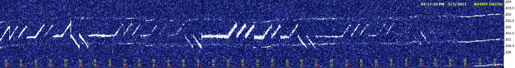
The short-hop path to Illinois and elsewhere has opened a little more over the past two days. As of Saturday afternoon, there were no more sightings of PCO (or PLM, WV, AZ, although MTI and FRC came through for a couple of minutes each late in the afternoon).
The best sighting of SIW slant was Friday afternoon, when I captured the attached image. Your browser will probably auto-resize it, so use the magnification tool and scroll as needed to see it all. Notice the different kinds of multipath present at different times, and the sudden enhancement, for which I have no explanation.
The best batch of SIW WSPR decodes are from mid-morning Saturday (frequency corrected for 22 m in this batch!):
1412 -25 -1.4  13.555402  0 K3SIW EN52 7
1424 -25 -1.8  13.555402  0 K3SIW EN52 7
1428 -25 -1.4  13.555404  0 K3SIW EN52 7
1436 -25 -2.4  13.555403  1 K3SIW EN52 7
1444 -20 -1.7  13.555404  0 K3SIW EN52 7
1452 -26 -1.3  13.555403  0 K3SIW EN52 7
1500 -18 -2.2  13.555404  0 K3SIW EN52 7
1504 -18 -1.6  13.555403  0 K3SIW EN52 7
1508 -23 -1.5  13.555403  0 K3SIW EN52 7
1512 -23 -1.6  13.555404  0 K3SIW EN52 7
1516 -24 -1.4  13.555404  0 K3SIW EN52 7
1552 -25 -1.7  13.555406 -1 K3SIW EN52 7
John
---------------------------------------------------------------
![]() File Attachment 1: 05may-siw.jpg
File Attachment 1: 05may-siw.jpg
Where the HiFERs Are; or, Children of the Night
Never thought I'd name a HiFER post with a parody of a children's book title and a line from Dracula, but there you are.
This little adventure actually began Saturday morning at sunrise, when I wrapped up my overnight session with EAR on 1750 meters. Tuning up to 22 meters, I caught a couple minutes of SIW slant and just a snippet of WSPR before the first skip zone closed up again and only EH remained, shortly joined by RY and later the rest of the gang. I thought to myself, "Hmm, I wonder how far before sunrise that started. For that matter, it's been a while since I watched for HiFERs very long after dark, too. Maybe I ought to charge everything up extra well and monitor from a couple hours before sunset until a couple hours after daybreak Sunday morning." And so, I did.
Up until dark, the Big Four at the watering hole (NC, USC, EH and RY) alternated in level with each other and had to contend with CODAR pretty much as they had done all afternoon. I heard MTI fairly well for a while in late afternoon, and saw incomplete traces of what might have been PBJ just a few Hz above.
After dark, I started seeing what I'll call "fractionals" for lack of a better term. They appear to be actual FSK signals, rather than IM products, but it's hard to tell. They're subject to so much QSB that I've not been able to tease out complete letters, let alone a full ID. Two of them reside between EH and USC, and the frequencies don't seem to match the intermod products that I often see due to the audio clipper when two or more of the Big Four get loud at the same time. I've got to keep studying this phenomenon and see if I can 100% verify whether they are real or just currently unexplained artifacts.
Around 9:57 PM CDT, RY finally faded and USC briefly became quite strong, simultaneously with QSB starting on NC. EH remained fair.
From 10:13-10:15 PM, my second window tuned below the watering hole caught a brief glimpse of WM! It's the first time I've seen that one in a couple of months now, despite the rare previous openings to SIW.
By 10:22, USC and NC were finally gone. EH began fading out and was mostly gone by 10:30. CODAR took over, and was absolutely terrible by 11 PM. At that point, my eyes were calling for a long spring nap and I figured the fun was over for the evening, so I retreated to the truck to snooze until first light...leaving the two QRSS3 captures running, of course. (I also had a QRSS30 session running, but, um, forgot to turn the capture on.)
Well, surprise, the fun was just beginning! At 11:24 PM, CODAR went away and the SIW duo suddenly showed up quite strongly to accompany the ghost of EH and wisps of NC. Images 0039 and 0040 show this time period.
During the midnight hour, not much went on, but some signals were present part of the time. A few minutes before 1 o'clock, NC was visible for a time, just barely within the top of the screen (must have been a cool night there). Then, something very peculiar: highly frequency-selective propagation! The lower frequency of EH's FSK was visible, but not the upper. SIW slant was visible, but not the WSPR version.
At 2:00 AM, both SIWs began to show up, becoming quite strong by 2:45 AM, when they were also accompanied by NC and a slight trace of USC. That went on with varying signal strengths (image 0065 was snapped during this time frame) until around 3:33 AM, when SIW began to fade out. NC and USC were also gone by 3:45 AM, and the captures remained thoroughly empty until 5:45 AM.
At that point, RY began to fade up out of nothing and was near dogbone strength in just four minutes. It continued at various levels until reaching heavy dogbone level at 6:26 AM (about 10 or 15 minutes after sunrise). USC showed up faintly just before then, but quickly faded, and even RY was gone by 6:33.
EH showed up around 6:59, followed by RY not long after. CODAR came back around 7:42 then got much worse after 7:45. USC returned about 8:05 AM.
I managed to copy MTI aurally through CODAR about 9:45 AM. After that, I could see but not quite hear what was recognizably PLM in its one-ID-then-5-second-dash mode. WM had left a couple of IDs by then as well.
Conclusion: Night time isn't just for LF any more! There were no unusual solar-terrestrial events that I could find yesterday, so this was probably not a one time deal. I need to be out there and conscious when the late-night breakdown of the first skip zone occurs, so I can also try for PCO, GNK, and the others that have eluded me so long in this phase of the solar cycle. I don't know if I have the strength to try again tonight, but I'll do it as soon as I am able.
John
---------------------------------------------------------------
![]() File Attachment 1: 0607maya0039.jpg
File Attachment 1: 0607maya0039.jpg
![]() File Attachment 2: 0607maya0040.jpg
File Attachment 2: 0607maya0040.jpg
![]() File Attachment 3: 0607maya0065.jpg
File Attachment 3: 0607maya0065.jpg
Saturday Hifers 6 May
At last a short chance for some listening, and decent signals near the watering hole
Seen, but not heard were: WM, RY, SIW and EH. The attached screenshot gives an indication of the conditions. Oddly, neither NC or USC were apparent.
None of the commonly audible signals, AZ, GNK or AA0RQ(PCO) surfaced during listening.
In the radio room, I have performed more experiments and tests on the loop aerial. A slight modification, and tinkering with a noise bridge I bought some while back showed the way towards a non-reactive 50 ohm load presented at its termination. Very fun! I did some walk-about testing this afternoon with it connected to PVC. It was definitely "getting out" despite being strung from the light fixture in the basement!
---------------------------------------------------------------
![]() File Attachment 1: capt11.jpg
File Attachment 1: capt11.jpg
![]() File Attachment 2: capt12.jpg
File Attachment 2: capt12.jpg
Re: Where the HiFERs Are
When I said Saturday night's reception "was probably not a one time deal," I may have been slightly optimistic. Last night everyone faded away by midnight and stayed gone until EH started showing up around sunrise. There were some ionosondes about an hour before sunrise, but that was it. (And a really annoying one not long after daybreak that I'll show you later.)
There was a repeat of WM during the evening before the Big Fade, and around 11:20 I finally heard GNK for the first time in ages. There were four solid IDs, three or four partials, and the remaining 6 or 7 minutes was only visual presence of keyed carrier.
I'll try one more time before Wednesday morning's storms are scheduled to arrive.
John
Re: Adding to my EAR collection.
Posted by Douglas Williams on May 10, 2017 at 18:23:21.
In reply to Adding to my EAR collection. posted by John Davis on May 06, 2017
You making a necklace? ;-)
Common mode choke
Posted by Steve Sykes on May 12, 2017 at 18:41:30.
I am wondering if anyone has a copy of the pdf of the common mode choke designed by Jack Smith at Cliftonlabs? I have a partially built choke and have the parts to build another one but can't remember the details of the cores used.
Since DX Engineering bought all of Jack's stuff, I haven't been able to find the file. I am trying to improve my kiwisdr for VLf and think this will halp.
Thanks, Re: Where the HiFERs Are (Third Night)
73
Steve KD2OM
Posted by John Davis on May 14, 2017 at 03:50:03.
In reply to Re: Where the HiFERs Are posted by John Davis on May 08, 2017
Somewhat Late News: The 72 hour HiFER marathon continued Monday night into Tuesday. The second night hadn't been at all productive from midnight to daybreak, but the third night showed somewhat more activity in the pre-dawn hours, even if not quite as much as the first night last Saturday. Alas, I was so worn out from the futile second night that I didn't even try to stay awake past 11 PM (CDT) the third night, and thus missed the opportunity to listen for anyone away from the watering hole.
Attached image 0051 shows the peak of the post-sunset hours about 10 PM CDT, with NC still present, USC gradually fading away, and EH and RY still dominating, plus faint SIW slant and snippets of SIW WSPR. NC and USC continued well past midnight, becoming especially strong from 1 AM until after 2 AM. USC started fading away then, and half an hour later, so did NC.
Just as NC was finally vanishing right before 3 AM, WM appeared for about 5 minutes, a little broken up but unmistakable:

There was nothing else for the next hours, then USC and NC began showing up intermittently again. and were quite strong by 5 AM. Forty-five minutes later, they were gone. NC started showing up again shortly after sunrise, EH began fading in about an hour after that, and RY joined in minutes later. USC returned a few minutes after 8 AM, and the typical daytime pattern set in. From 11 o'clock onward, CODAR got pretty rough.
With more flooding thunderstorms moving in before Wednesday morning, that was the last day of the marathon.
John
---------------------------------------------------------------
![]() File Attachment 1: 0809maya0051.jpg
File Attachment 1: 0809maya0051.jpg
![]() File Attachment 2: 0809may-WM.gif
File Attachment 2: 0809may-WM.gif
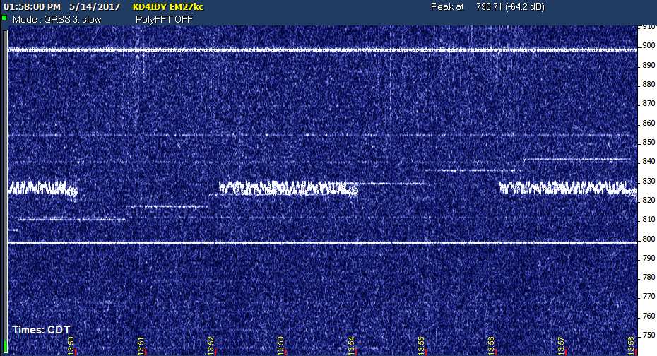
Lucky 13th--MTI _and_ PBJ, plus PLM
This Saturday afternoon was very productive. The regulars were present at the watering hole, but when I tuned up to look for MTI, both it and PBJ were present at audible levels (at least for a while)!
Later in the 3 o'clock (CDT) hour, I had a couple of good receptions of PLM, stiched together below. Three of the IDs were fully audible, and three were good enough to copy one or two letters. Some of the brighter 5-second dashes were also amply audible.
During the evening I encountered a couple decodes of SIW WSPR, the former before dark and the latter an hour and a half after sunset.
0036 -21 -1.5  13.555405  0 K3SIW EN52 7
0244 -22 -1.9  13.555403 -1 K3SIW EN52 7
There were also captures of several SIW slant IDs during the evening, which I will process later. No all-night session for me tonight, though!
John
---------------------------------------------------------------
![]() File Attachment 1: 13mayMTIPBJ.gif
File Attachment 1: 13mayMTIPBJ.gif
![]() File Attachment 2: 13mayPLM.gif
File Attachment 2: 13mayPLM.gif
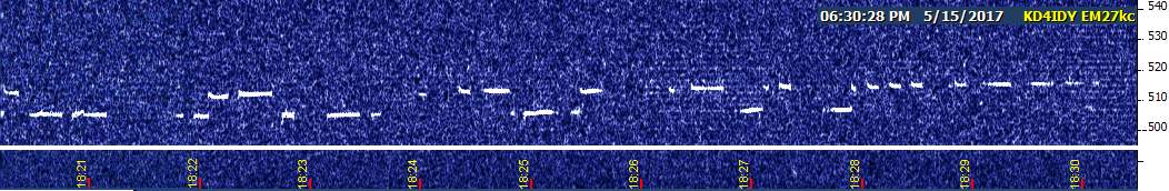
Today's 2200 Meter Project
Last night I thought I'd try once more for TAG on 1750 m after I ended my evening of HiFER monitoring around 11 PM, but QRN was clearly too bad, as it has been the last several times I tried. Since our current local dry spell only has another 48 hours to go, tops, I wondered what other LF monitoring effort I could undertake today with a reasonable chance of success. Recalling that it had been a few months since I attempted a 24 hour capture of WH2XND, I decided that might be worthwhile.
I started this afternoon about 40 minutes prior to local solar noon. The last capture shown below was with solar noon midway between here and Arizona, still plenty solid.
(BTW, is anyone else seeing that frequency-stepping signal?)
It's a very quiet day so far, with median QRN well below S1 and rare peaks to S2 or S3. The XND signal appears to be somewhere between S0 and S1. (Tonight will probably once again exceed S9 continuously, which is enough to wipe out any Part 15 stations...even SIW's nighttime skywave, when it's on...but shouldn't be enough to overwhelm XND unless QSB is too deep at times during the night.)
Although WSPR reports a "magicked up" signal-to-noise ratio of around -10 dB in most of the decodes below, that's a calculated value relative to an arbitrarily wide assumed receiver SSB noise bandwidth. According to Argo, though, typical signal levels during each transmission were around -51 dB, while the background noise showed -71 or lower during the gaps between transmissions; in other words, +20 dB SNR in the necessary WSPR-2 communications bandwidth. Even in the noise bandwidth of my CW filter, with the assorted PLC signals that you see, the CW ID at the end of each transmission was plainly audible.
Here are the first 80 minutes of decodes. The one for the 1832 (UTC) time slot is AWOL because I idiotically inadvertently disconnected the power cord for the antenna buffer from the storage battery for a couple of minutes.
1740 -11 -0.9   0.137527  0 WH2XND DM33 40
1744 -10 -0.7   0.137527  0 WH2XND DM33 40
1748 -10 -0.8   0.137527  0 WH2XND DM33 40
1752 -10 -0.7   0.137527  0 WH2XND DM33 40
1756 -10 -0.9   0.137527  0 WH2XND DM33 40
1800  -9 -0.8   0.137527  0 WH2XND DM33 40
1804 -10 -1.0   0.137527  0 WH2XND DM33 40
1808 -10 -1.0   0.137527  0 WH2XND DM33 40
1812 -10 -0.9   0.137527  0 WH2XND DM33 40
1816 -10 -0.9   0.137527  0 WH2XND DM33 40
1820 -10 -0.8   0.137527  0 WH2XND DM33 40
1824 -11 -1.0   0.137527  0 WH2XND DM33 40
1828 -11 -1.0   0.137527  0 WH2XND DM33 40
1836 -10 -0.8   0.137527  0 WH2XND DM33 40
1840 -10 -1.0   0.137527  0 WH2XND DM33 40
1844 -11 -1.0   0.137527  0 WH2XND DM33 40
1848 -10 -0.8   0.137527  0 WH2XND DM33 40
1852 -11 -1.0   0.137527  0 WH2XND DM33 40
1856 -12 -0.9   0.137527  0 WH2XND DM33 40
I've uploaded these to WSPRnet, and will continue doing so every few hours during the run of this experiment. I'd prefer to do it in real-time, but there's no Internet service out in the field.
John
(P.S. - A reminder to Authenticated Authors: you too can do everything I've done in this message, including displaying an uploaded file within the message. To find out how, use the Authenticated Authors link on the main Message Board page, then jump to the Reference Page.)
---------------------------------------------------------------
![]() File Attachment 1: 14mayXND1.jpg
File Attachment 1: 14mayXND1.jpg
Re: Today's 2200 Meter Project
Things were going fairly well until after 5 PM CDT, when XND's signal began to deteriorate and noise began to rise. The Argo captures show the signal strength diminishing somewhat before the QRN got so bad, interestingly. It's the result of severe thunderstorms from southwest Kansas down into the Texas panhandle.
Currently looking to see which happens first... the nighttime skywave increasing to a level that competes with the noise (a median level of S8 and excursions from S3 to +20), or the severe storms dying out. Even at worst, enough of the WSPR signal remained visible under the noise that I estimate QRSS10 would have given reasonable copy. We'll see what happens next.
John
1900 -12 -1.0   0.137527  0 WH2XND DM33 40
1904 -11 -1.0   0.137527  0 WH2XND DM33 40
1908 -11 -0.9   0.137527  0 WH2XND DM33 40
1912 -12 -0.9   0.137527  0 WH2XND DM33 40
1916 -12 -1.0   0.137527  0 WH2XND DM33 40
1920 -12 -1.0   0.137527  0 WH2XND DM33 40
1924 -12 -1.0   0.137527  0 WH2XND DM33 40
1928 -11 -0.9   0.137527  0 WH2XND DM33 40
1932 -11 -0.9   0.137527  0 WH2XND DM33 40
1936 -12 -0.9   0.137527  0 WH2XND DM33 40
1940 -11 -1.0   0.137527  0 WH2XND DM33 40
1944 -11 -0.9   0.137527  0 WH2XND DM33 40
1948 -11 -0.9   0.137527  0 WH2XND DM33 40
1952 -11 -0.9   0.137527  0 WH2XND DM33 40
1956 -11 -1.0   0.137527  0 WH2XND DM33 40
2000 -12 -1.0   0.137527  0 WH2XND DM33 40
2004 -12 -1.0   0.137527  0 WH2XND DM33 40
2008 -12 -1.0   0.137527  0 WH2XND DM33 40
2012 -12 -1.1   0.137527  0 WH2XND DM33 40
2016 -13 -1.1   0.137527  0 WH2XND DM33 40
2020 -13 -1.0   0.137527  0 WH2XND DM33 40
2024 -13 -1.0   0.137527  0 WH2XND DM33 40
2028 -13 -1.0   0.137527  0 WH2XND DM33 40
2032 -13 -0.9   0.137527  0 WH2XND DM33 40
2036 -14 -1.1   0.137527  0 WH2XND DM33 40
2040 -13 -1.1   0.137527  0 WH2XND DM33 40
2044 -15 -1.0   0.137527  0 WH2XND DM33 40
2048 -15 -1.1   0.137527  0 WH2XND DM33 40
2052 -16 -0.9   0.137527  0 WH2XND DM33 40
2056 -16 -1.0   0.137527  0 WH2XND DM33 40
2100 -17 -1.1   0.137527  0 WH2XND DM33 40
2104 -16 -1.0   0.137527  0 WH2XND DM33 40
2108 -15 -1.1   0.137527  0 WH2XND DM33 40
2112 -16 -1.1   0.137527  0 WH2XND DM33 40
2116 -16 -1.1   0.137527  0 WH2XND DM33 40
2120 -16 -1.0   0.137527  0 WH2XND DM33 40
2124 -17 -1.1   0.137527  0 WH2XND DM33 40
2128 -17 -1.1   0.137527  0 WH2XND DM33 40
2132 -16 -1.2   0.137527  0 WH2XND DM33 40
2136 -18 -1.1   0.137527  0 WH2XND DM33 40
2140 -18 -1.2   0.137527  0 WH2XND DM33 40
2144 -20 -1.0   0.137527  0 WH2XND DM33 40
2148 -20 -1.1   0.137527  0 WH2XND DM33 40
2152 -21 -1.1   0.137527  0 WH2XND DM33 40
2156 -21 -1.1   0.137527  0 WH2XND DM33 40
2200 -23 -1.2   0.137527  0 WH2XND DM33 40
2204 -22 -1.2   0.137527  0 WH2XND DM33 40
2208 -22 -1.2   0.137527  0 WH2XND DM33 40
2212 -22 -1.3   0.137527  0 WH2XND DM33 40
2216 -23 -1.2   0.137527  0 WH2XND DM33 40
2220 -22 -1.2   0.137527  0 WH2XND DM33 40
2224 -22 -1.2   0.137527  0 WH2XND DM33 40
2228 -24 -1.2   0.137527  1 WH2XND DM33 40
2232 -26 -1.1   0.137527  0 WH2XND DM33 40
Re: Today's 2200 Meter Project
Well, so much for an uninterrupted 24 hour XND monitoring session, even disregarding the storm QRN! He seems to be experiencing technical difficulties and apparently has been QRT most of the time since the end of the 0308 UTC time slot, which seems to have been interrupted during the CW ID at the end.
The signal barely overcame the QRN nearly an hour after sunset at 0208 for a single decode. It continued barely visible on Argo, then became decodable again for the 2252 time slot. The skywave signal was then doing quite well despite the unchanged static levels, right up until the end of the 0308 slot.
After an hour or so, I figured I'd go up to 22 m to look around then probably pack up for the night. I was rewarded with FRC for the first time in several days... and quite a strong, audible signal at that! I then transferred all my files to the memory stick, set up my Argo sessions for tomorrow's date, and checked the computer time clock against WWV before powering down the radio and computer for the return to town.
Right before shutting down, though, I checked 2200 m one more time and heard a few seconds of distinctive signal; then later, a few more. In the past hour there have been a few transmissions of up to a minute in length before it cuts off. I don't know if he'll be back full time tonight or not; but I'll watch a little longer, just in case.
John
0208 -25 -0.9   0.137527  0 WH2XND DM33 40
0252 -19 -1.0   0.137527  0 WH2XND DM33 40
0256 -15 -1.1   0.137527  0 WH2XND DM33 40
0300 -15 -1.0   0.137527  0 WH2XND DM33 40
0304 -16 -1.0   0.137527  0 WH2XND DM33 40
0308 -14 -1.1   0.137527  0 WH2XND DM33 40
2200M WSPR overnight
I gave WSPR-2 a go overnight on 2200M, and was rewarded with:
0300 -25 -0.9 0.137528 0 WH2XND DM33 40
0304 -28 -0.9 0.137528 0 WH2XND DM33 40
Re: 2200M WSPR overnight
73, J.B., VE3EAR
Posted by John Davis on May 15, 2017 at 16:01:20.
In reply to 2200M WSPR overnight posted by John Bruce McCreath on May 15, 2017
Good work, JB. The very next transmit slot (0308) turned out to be the last more-or-less full transmission of the night for XND. I saw (and heard) the signal abruptly start up and shut down a few more times, sometimes on only for a few seconds, and twice for a minute or so. After the 0500 hour, there were apparently no more attempts, and he was still off at mid-morning.
John D
Hifer aerial experiments
Posted by ed holland on May 15, 2017 at 17:45:27.
Hi folks,
Found time for a little listening and experimentation this weekend, mostly yesterday. Enjoy the following ramble or, it you're wise - ignore it!
Introduction:
I have been doing some tinkering with loop aerials lately. The present example is approximately 12 ft of #12 solid wire on a square frame of white PVC pipe. Some experimentation with my trusty noise bridge enabled a coupling loop to be configured so that a 50 ohm impedance is presented to the coax. A ceramic bodied 15 pF trimmer at the top of the loop permits tuning from ~6 MHz to ~15 MHz and is the only purchase made specifically for the project. For the latest experiments, the loop was suspended from a tree, borrowing the feeder for my long-wire. This disposition is somewhat close to the house, and not especially "out in the clear", but does allow the loop tuning to be trimmed, which is quite demanding on account of the sharp peak, and the need to use a long trimmer tool so as to minimise one's influence on the loop due to stray capacitance. The loop was tuned in situ, on transmit, using a small portable receiver to detect peak output.
Experiment 1: Receive
In this endeavour, I compared the loop against the "random wire dipole" that has become the de facto standard for 22m HiFER reception. Firstly, I noticed a higher (atmospheric) noise floor against the dipole. Not much man made "hash" that I could identify. Attention turned to the "Watering Hole" (though I did try the top and bottom of the bands as always). The dipole showed some activity from both SIW stations, and IIRC WM. Switching to the loop brought traces that were obviously a continuation, but would be hard to have logged without the previous observations.
Intermission:
I decided to experiment with feeding PVC's signal to the loop, to compare the received signal from the receive dipole with the numbers I see from PVC's usual (separate) dipole. I'd played before (indoors) and seen S9 +30 dB, now, curiously, the signal was swinging (hint) from barely S9 to S9 +20 dB. Then I realised the swing had a fairly consistent period/time constant. I visited the loop and saw the issue immediately. With a little stabilisation (another piece of string) I arrested the twisting motion. Also, I arranged the loop so that in theory, it's pattern should match the direction of the dipole. Result: S9 +30 dB and steady, very similar to the dipole.
Return to receive:
The re-oriented loop showed improved sensitivity to the HiFERs that could also be seen with the dipole. It would be instructive to monitor both simultaneously, as an A/B comparison is at the mercy of the short timescale variations in propagation. However, the loop's performance is very encouraging, especially considering its compact size. It might be expected that better results could be obtained with improved siting. The dipole against which the comparison took place has it's apex in a tree at ~20 ft and the ends > 6 ft above ground. By contrast the loop center was perhaps 6 ft above ground, but further down the hill, and potentially affected by other nearby structures - quite a disadvantaged site in my opinion.
This work provides anecdotal evidence to support the enthusiasm for tuned loops that I have seen from various internet sources. Attention to a few details appears to show that these aerials are suitable for aspects of HiFER work. One aspect that has not been addressed is the desire/requirement to adjust tuning remotely for easy optimisation, and convenient use on a wider range of frequencies.
PVC is transmitting from the loop this week, so reports from 13,558.400 would be very welcome.
Regards,
Ed
U3S and N3ZI Kits
Posted by Frank Lotito on May 15, 2017 at 18:04:09.
On this bulletin board I have seen postings about the QRP Labs U3S TX kit for use as a VFO. In recent personal correspondence on VFO's the writer's used this kit to salvage older commercial equipment in which the rig's exciter failed and service was long discontinued by the OEM and its agents. In my own shack a few years back I settled in on the N3ZI DDS VFO kit. I have used my N3ZI kits (plural) for my 600 / 630 meter transmitter buildups, as well as for classic era boat anchors and home brewed tube and solid state MF and HF transmitter applications. I have yet to use the N3ZI kits for any type of receiver project. On occasion I've stumbled across VFO kits from other manufacturers. I have no experience with those kits.
Does anyone have subjective comments on the U3S vs DDS kits' performance at various frequencies? Has anyone performed "quantitative comparative" measurements on these kits? My specific interest is for LF / MF / HF transmitter application.
Thank you 73 Frank K3DZ / WH2XHA Re: U3S and N3ZI Kits
Posted by John Davis on May 16, 2017 at 04:07:03.
In reply to U3S and N3ZI Kits posted by Frank Lotito on May 15, 2017
Actually, the U3S is a lot more than a VFO. Much of its functionality would be wasted in such an application, and it has ergonomic limitations.
For a transmitter VFO, either kit could, in principle, do the job. However, there is one operational difference worth noting: the N3ZI kit is tunable with a knob, whereas the U3S must be programmed with pushbutton switches...not a very "variable" VFO. The basic QRP Labs Si5351A synthesizer board under control of a microprocessor might be a better option if only a VFO is desired; and in fact, they do offer a VFO/Signal Generator Kit that is exactly that, complete with rotary encoder and knob.
Receiving is a tougher job. In terms of spectral purity, as we've discussed before, receiver sensitivity and dynamic range are highly dependent on L.O. noise. The discussion by G3ZIL in one of the articles at the QRP Labs site shows that the Si5351A chip (with a really, really clean power source) is only about 6 dB noisier than a reasonable quality crystal oscillator. In practice, that means a carefully designed receiver made with that chip as the L.O. might be able to achieve sensitivity in the -120 dBm range--not the more desirable -130 dBm or better, but not terrible.
On the other hand, the N3ZI kit uses an AD9834 DDS chip, whose noise performance is limited by its 10-bit internal DAC to a not-at-all-impressive 60 dB broadband. Noise within ±200 kHz is better by several dB, but only in the most extraordinary cases with select devices does it approach the -74 dBc value optimistically given in the N3ZI web page. Plenty good for a transmitter...pretty lame for a DXing receiver.
John
Re: 2200M WSPR overnight
Posted by John Davis on May 16, 2017 at 04:35:11.
In reply to Re: 2200M WSPR overnight posted by John Davis on May 15, 2017
No further transmissions before dark tonight (Monday), so I tuned up to 22 m for a while and then packed up and came home. Next monitoring session may be several days away, after the next two rounds of storms.
The Ides of May--PBJ with a side of FSK?
Posted by John Davis on May 17, 2017 at 04:06:50.
Sorry it takes so long sometimes to get these reports posted, but there was an odd capture for sure yesterday evening. First, a look at yesterday morning, when everything appeared relatively normal:
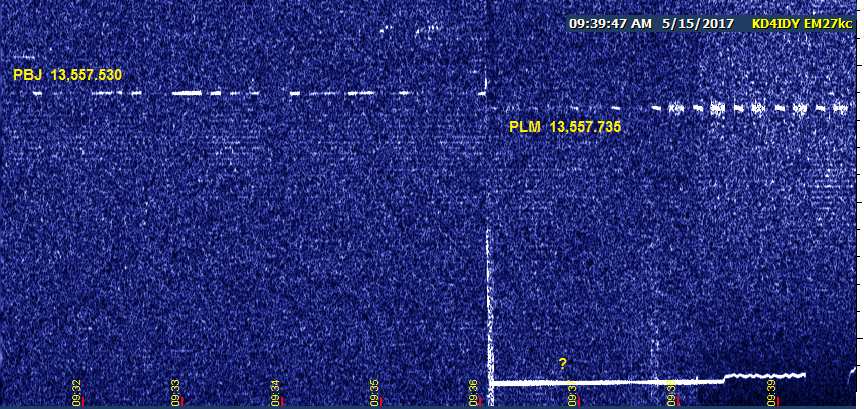
When I checked back in the evening, I was momentarily encouraged to see a much improved signal level--but then things got weird!
FWIW, this is the second or third day recently when PBJ has come through without being accompanied by MTI at least part of the time.
Nest, I did a band scan and (much to my surprise) came up with a prolonged daylight reception of GNK. Only part of the IDs were audible, but some were quite clear.
Right after that, I checked with FRC briefly and got several partial IDs and one or two complete ones.
John
---------------------------------------------------------------
![]() File Attachment 1: 15may01.jpg
File Attachment 1: 15may01.jpg
![]() File Attachment 2: 15mayPBJ2.jpg
File Attachment 2: 15mayPBJ2.jpg
![]() File Attachment 3: 15mayGNK.gif
File Attachment 3: 15mayGNK.gif
The 2200 Meter Project Resumes, Maybe
Since we escaped significant rainfall from last night's storms and further activity is not expected here until tomorrow night, I decided to play truant from my LOWDOWN preparation duties for part of the day and resume monitoring XND at local noon today. Although the WSPR signal has been mostly visible and sometimes audible, the type of QRN being generated by near-severe storms in Nebraska and northern Kansas (currently under tornado watches) is the kind that can disrupt WSPR decoding even in the presence of otherwise adequate signal.
The attached file shows the one lone decode between 12:00 and 12:30 PM CDT, and the Argo and WSPR 2.12 waterfall displays of the signal. The CW ID at the end of each transmission is audible most of the time, but too broken up to copy. A QRSS3 signal at XND's power level would be 50% or better copy by my estimate, and a QRSS10 signal should be solid copy.
What I'm trying to establish is ground wave performance of 2200 m in the presence of typical summertime electrical activity, but the severe stuff with its higher percentage of noise fill-in is making this difficult. Let's hope that low pressure system moves on away in time to give me 24 more or less "normal" hours before the next system moves in tomorrow night.
John
---------------------------------------------------------------
![]() File Attachment 1: 17may1.jpg
File Attachment 1: 17may1.jpg
Re: Common mode choke
I do.
dl.dropboxusercontent.com/u/33457409/Common%20Mode%20Choke%20Assembly.pdf
Also, Jack responded with this after I asked him what I should do for a common mode choke if I was only interested in LF/VLF reception:
"For a common mode choke, I would pick up 10 of Steward 40T1417-10H cores (DigiKey PN 240-2537-ND) and super glue them into two equal stacks of 5 cores. Then wind as many turns of the 75 ohm cable as you can get through them. (Actually, I would probably use RG-174 since the RG6 cable is (a) too large in diameter and (b) too stiff to easily work with)."
I constructed one to his specifications.
Re: The 2200 Meter Project Resumes--Not
Posted by John Davis on May 18, 2017 at 04:31:45.
In reply to The 2200 Meter Project Resumes, Maybe posted by John Davis on May 17, 2017
The storms got worse...median QRN level went from a median value of S7 or S8 with excursions from S1 to +30, up to S9+15 with peaks to +30 just an hour or so later. Not even the PLCs were coming through that continuous racket. I monitored HF for a couple more hours before shutting down, but there was still no sign of XND. Since we're expecting local possibly severe thunderstorms here in less than 24 hours, that pretty well precluded a 24 hour session. Maybe next week....
1716 -24 -0.6   0.137527  0 WH2XND DM33 40
1744 -21 -2.3   0.137527  0 WH2XND DM33 40
1748 -20 -0.7   0.137527  0 WH2XND DM33 40
1812 -22 -0.8   0.137527  0 WH2XND DM33 40
Re: The Ides of May--PBJ with a side of FSK?
Saw a little of what was probably PBJ today, but no frequency jumps. GNK came through for nearly half an hour before 6 PM CDT, and PLM was visible but barely audible before that.
Re: Common mode choke
Posted by Steve KD2OM on May 18, 2017 at 21:31:56.
In reply to Re: Common mode choke posted by Doug KB4OER on May 17, 2017
Thank you Doug, now I can finish the choke I started. I think I will also make the one you did as well. It looks like RG-174 would be much better. I wonder how does it work, does it improve VLF/LF reception?
73 Re: Common mode choke
Steve KD2OM
Posted by Lee on May 19, 2017 at 05:12:57.
In reply to Common mode choke posted by Steve Sykes on May 12, 2017
Looking thru my notes found this. From KB4OER glue five 40T1417-10H cores together. Digi-Key part # 240-2537-ND. Wrap as many turns as you can fit of RG-174 thru the cores. Ta-Da. Common Mode Choke.
Lee KE6PCT
TAG Off
Posted by John, W1TAG on May 22, 2017 at 01:25:48.
Lowfer TAG (185.297 - Raymond, ME) is off the air until late October. This will allow the use of the antenna for other purposes over the summer. Thanks for the reports this past season.
John, W1TAG
RY Off & On
Posted by John, W1TAG on May 22, 2017 at 01:31:56.
Hifer RY (13555.415 - Raymond, ME) will be operating intermittently until the end of October, as I take advantage of the excellent 20 meter antenna. If anyone wants some signal to play with, let me know.
John, W1TAG
Re: Common mode choke
Posted by Doug KB4OER on May 25, 2017 at 18:53:26.
In reply to Re: Common mode choke posted by Lee on May 19, 2017
I can't take credit for that, Lee. That was what the late Jack Smith (Clifton Labs) suggested to me.
Re: Common mode choke
Posted by Doug KB4OER on May 25, 2017 at 18:56:41.
In reply to Re: Common mode choke posted by Steve KD2OM on May 18, 2017
Glad to help, Steve. As with all things in this hobby, the answer is going to be "it depends on your particular situation". :-)
Have fun with it and I hope it helps.
Re: Common mode choke
Posted by Dave Childs on May 25, 2017 at 19:03:23.
In reply to Re: Common mode choke posted by Doug KB4OER on May 17, 2017
I haven't had any luck finding those toroid cores from using those P/Ns at either DigiKey's or Steward's web sites. Is there any reason that 5 of Amidon's T-225-3 powdered iron toroid core won't work satisfactorily instead? Its freq. range is 50-500KHz. & I/D=1.4 in. & ht.=0.55 in. The rest of its specs are here: http://www.amidoncorp.com/t225-3/ I don't have any info on the core y'all mentioned so I can compare them. TIA!
FL experimental circuit/mode/freq
Posted by Dave N4EF on May 25, 2017 at 23:14:36.
I've launched a new transmitter on 13555.520 KHz last week in QRSS3 CW sending "FL". It's in breadboard form now -- I will make some circuit changes in the next few days on the bandpass filter and let it run a few more weeks. The transmitter is in a room in my house that is subject to wide swings in ambient temperature so I suspect the frequency may drift accordingly.
If all seems well after the design changes, I'll rebuild it in a more permanent form and activate it on a temperature controlled environment.
The FSKCW "FL" on 13555.465 KHz has been temporarily deactivated.
Dave HiFERs Friday 5/26
Central Florida
Posted by John Davis on May 26, 2017 at 17:10:05.
WM was surprisingly good at 9:30 AM CDT, with the CW IDs quite audible. EH was also present at the watering hole, along with a very solid USC and a rather weak NC. (At that time, NC was right on top of 13,555.520, but there was no sign of FL.) SIW slant was doing well and SIW WSPR was visible; hopefully enough to yield some decodes by now.
GNK was good copy at times and down in the noise at others, with a rather fast and very wide ranging QSB cycle.
Others attempted but not see or heard: WV, MTI, PBJ, PLM, PCO, FRC. Will keep trying today.
John
Re: Common mode choke
Posted by Steve KD2OM on May 26, 2017 at 20:14:01.
In reply to Re: Common mode choke posted by Dave Childs on May 25, 2017
Dave,
I think the problem with using those cores is that the AL number is way off. The AL of the Amidon toroid is 425 and the suggested core is 13440. You wouldn't be able to put enough turns to do any choking.
This page that I found on line shows the cores. PN 240-2537-ND
http://dkc3.digikey.com/PDF/CN081/P1453.pdf
I have contacted them about this but haven't heard back yet.
73
Steve KD2OM
Re: Common mode choke
Posted by Steve KD2OM on May 26, 2017 at 21:40:58.
In reply to Re: Common mode choke posted by Steve KD2OM on May 26, 2017
Digikey got back to me very quickly. The toroids suggested by Jack Smith are now a non stocking item now so minimum quantities and lead times apply. They suggested these as a substitute:
Digikey PN 495-3868-ND and 240-2287-ND. The 495 part looks almost an exact replacement, $3.82 each. The other one uses different specs on their data sheet but must be about the same, $2.67 each.
Both are stocked and have good quantities available.
Steve KD2OM
Re: HiFERs Friday 5/26
Posted by John Davis on May 26, 2017 at 23:54:34.
In reply to HiFERs Friday 5/26 posted by John Davis on May 26, 2017
The opening from Illinois lasted until about 10 minutes after local solar noon for SIW WSPR and another 10 minutes or so (to 1841 UTC) for slant mode, and then someone turned the ionosphere switch off. Just a couple of bogus decodes for the remainder of the afternoon after that, arising from intermod products between EH and NC. Before that, though:
1456 -18 -1.8  13.555404  0 K3SIW EN52 7
1500 -21 -1.3  13.555404  0 K3SIW EN52 7
1504 -18 -1.2  13.555404  0 K3SIW EN52 7
1508 -20 -1.1  13.555404  0 K3SIW EN52 7
1512 -19 -0.9  13.555404  0 K3SIW EN52 7
1516 -19 -1.8  13.555399  0 K3SIW EN52 7
1524 -22 -1.2  13.555405  0 K3SIW EN52 7
1528 -20 -1.2  13.555405  0 K3SIW EN52 7
1540 -20 -1.8  13.555405  0 K3SIW EN52 7
1544 -19 -1.5  13.555405  0 K3SIW EN52 7
1548 -24 -1.3  13.555405  0 K3SIW EN52 7
1552 -19 -1.1  13.555405  0 K3SIW EN52 7
1556 -22 -1.2  13.555407  0 K3SIW EN52 7
1600 -22 -1.9  13.555406  0 K3SIW EN52 7
1604 -20 -1.4  13.555406  0 K3SIW EN52 7
1608 -19 -1.4  13.555406  0 K3SIW EN52 7
1612 -22 -1.1  13.555406  0 K3SIW EN52 7
1616 -23 -1.0  13.555406  0 K3SIW EN52 7
1620 -18 -2.0  13.555406  0 K3SIW EN52 7
1624 -18 -1.5  13.555406  0 K3SIW EN52 7
1628 -22 -1.2  13.555406  0 K3SIW EN52 7
1632 -24 -1.3  13.555406  0 K3SIW EN52 7
1636 -22 -1.1  13.555406  0 K3SIW EN52 7
1640 -19 -1.1  13.555407  0 K3SIW EN52 7
1644 -22 -1.3  13.555407  0 K3SIW EN52 7
1648 -20 -1.1  13.555407  0 K3SIW EN52 7
1652 -21 -1.1  13.555407  0 K3SIW EN52 7
1656 -20 -2.0  13.555407  0 K3SIW EN52 7
1700 -22 -1.5  13.555407  0 K3SIW EN52 7
1704 -21 -1.4  13.555407  0 K3SIW EN52 7
1708 -23 -1.3  13.555407  0 K3SIW EN52 7
1712 -20 -1.2  13.555407  0 K3SIW EN52 7
1716 -21 -1.3  13.555407  0 K3SIW EN52 7
1720 -19 -1.4  13.555407  0 K3SIW EN52 7
1724 -22 -1.4  13.555407  0 K3SIW EN52 7
1732 -19 -1.1  13.555407  0 K3SIW EN52 7
1736 -22 -1.0  13.555407  0 K3SIW EN52 7
1740 -23 -1.4  13.555407  0 K3SIW EN52 7
1744 -18 -1.3  13.555407  0 K3SIW EN52 7
1748 -22 -1.4  13.555407  0 K3SIW EN52 7
1752 -23 -1.3  13.555407  0 K3SIW EN52 7
1756 -16 -2.2  13.555407  0 K3SIW EN52 7
1804 -15 -1.4  13.555407  0 K3SIW EN52 7
1808 -25 -1.2  13.555409  0 K3SIW EN52 7
1812 -19 -1.2  13.555407  0 K3SIW EN52 7
1816 -17 -2.2  13.555407  0 K3SIW EN52 7
1820 -24 -1.6  13.555407  0 K3SIW EN52 7
1824 -19 -1.4  13.555409  0 K3SIW EN52 7
1828 -28 -1.4  13.555407  0 K3SIW EN52 7
1832 -22 -1.2  13.555407  0 K3SIW EN52 7
---------------------------------------------------------------
![]() File Attachment 1: 26may-SIW.gif
File Attachment 1: 26may-SIW.gif
Propagation prediction maps
Proppy website is an easy to use dashboard similar to the VOACAP HF prediction website and may be useful for predicting the prime times for 22 m hunting. Re: Propagation prediction maps
https://soundbytes.asia/proppy/
Posted by Chuck, N1KGY on May 27, 2017 at 23:21:34.
In reply to Propagation prediction maps posted by Dave N4EF on May 27, 2017
Nice find, Dave. Thanks for sharing!
Re: Common mode choke
Posted by Dave Childs on May 28, 2017 at 06:11:36.
In reply to Re: Common mode choke posted by Steve KD2OM on May 26, 2017
Thanks Steve! Apparently I should've contacted DigiKey or Steward about replacements or specs. I'll try to do better next time!
Re: HiFERs Friday 5/26 (into 5/27)
Posted by John Davis on May 28, 2017 at 17:25:21.
In reply to Re: HiFERs Friday 5/26 posted by John Davis on May 26, 2017
First off, I have now corrected the WSPR frequencies in the previous report in this thread. I'd thought on Friday that I might try for XND on 2200 meters, but the storm QRN was already too high, even with the storms 24 hours away from here; and I forgot to reset the "dial frequency" to 22 m. Glad I didn't get around to sending those to WSPRnet!
After the Friday afternoon report, things settled down to only the usual three at the watering hole for most of the afternoon (EH, NC, USC) plus codar. At 4:58 PM CDT, SIW slant magically appeared with minor traces of the WSPR signal, before disappearing half an hour later. After another half hour, both abruptly returned. WM also re-appeared shortly thereafter, but I don't know exactly when because the capture on that Argo screen accidentally got turned off.
Around 8:40 PM, I noticed that the Illinois signals were all pretty stable, so I thought it might be a good opportunity to check for other relatively close signals. GNK was pretty good, but no sign of PLM, PCO, MTI, PBJ, or even the more distant FRC.
General fading started around 9 PM, and everybody was nearly gone by 11 PM. SIW slant exhibited dual and triple path propagation during some of that time with Doppler shifts as high as 0.5 Hz, as shown in the attached capture. After that, only mild to moderate codar was present for about an hour.
At 12:10 AM, the "machine gun" ionosondes took over until 2:25 AM, with anywhere from two to half a dozen soundings per minute. For about 15 minutes straddling 1:00 AM, there was a faint, noisy trace of an "SI" in slant mode and a couple indications of WSPR, but no hope of decoding it in that noise.
For the next three hours after the racket ended, there wasn't much...just a few minutes at a time of EH or NC or USC faintly visible, then back to nothing. More soundings resumed at 5:45 AM on the 27th (CDT), but fortunately not as many. NC, then EH, and then USC started showing up intermittently after 6 AM, returning to a typical daytime pattern before 7 AM.
I had some further WSPR decodes from SIW before mid-morning and saw WM again from about 9:30 to 9:42 AM. A little after 10 AM, I tuned up a bit and saw MTI and PBJ weakly, sometimes getting partial copy of MTI by ear. This is shown in the other attachment. Still no sign of PLM. I did try for PCO and was hopeful for a moment, but once again it turned out just to be beat notes of some close-spaced carriers right there.
That ended that particular 24 hour session because strong storms were building and moving in this direction. We lucked out and missed the worst of it. If no severe storms develop along the Gulf Coast to create excess QRN, maybe I can try for XND today. Otherwise, I might do some more HF monitoring.
---------------------------------------------------------------
![]() File Attachment 1: 26maySIW2.jpg
File Attachment 1: 26maySIW2.jpg
![]() File Attachment 2: 27mayMTIPBJ.jpg
File Attachment 2: 27mayMTIPBJ.jpg
SAQ Transmission�on Alexanderson Day Cancelled
News from
the Alexander Association
Grimeton SAQ Veteran Radio Friends
www.alexander.n.se
SAQ Transmission�on Alexanderson Day Cancelled
We regret�to announce that the scheduled transmissions on Alexanderson Day, July 2nd 2017,�with the old Alexanderson alternator SAQ on VLF17.2 kHz, at�the World Heritage Grimeton Radio Station, Sweden has been cancelled, due to ongoing maintenance work.
The Alexanderson Day will offer an exiting range of activities (details�will follow), including two startups�of the Alexanderson alternator, including a local, not aired transmission at the following times:
- Startup�@10.30 (08.30 UTC) with a local message @11.00 (09.00 UTC).
- Startup�@13.30 (11.30 UTC) with a local message @14.00 (12.00 UTC).
Both of these startups will be streamed on our YouTube Channel. No QSL-cards will be given this time and no list of Reports will be constructed but we look forward to your comments and stories (images appreciated) to�info@alexander.n.se.�
//The Alexander association team @Grimeton, Sweden Beacon Operation
Posted by Frank Lotito on May 29, 2017 at 20:05:21.
The present on-line e-CFR edition for amateur radio communications has a section on beacon operation, 47CFR97 article 203. I am having trouble interpreting subparagraph (d) which speaks of "automatic control" and specifies a minimum permitted frequency of 28.20 MHz for "automatic control."
QUESTION #1: Does this mean for all other amateur bands, including the pending 600 and 2200 bands "automatic control" is not permitted?
QUESTION #2: I assume beacon operation on "any" amateur frequency that the "control operator" (licensee) is authorized to participate on, beacon operation is permitted if the control operator is present and can "kill the beacon transmission" if something goes amiss? For example, a beacon transmitting someplace on the anticipated 630 or 2200 meter bands? Or on the 160 meter band? 30 meter band? 17 meter band? It is understood a reasonable attempt is made by the control operator to insure non-interference with normal on-going transmissions for that band, and as a courtesy, adhere to gentlemen's agreements for band plans.
Probably the key words in 47CFR97.203 is the FCC's meaning of the words "automatically controlled" and "control operator." For example, when I use my 630 meter transmitter in the beacon mode I use a dedicated PIC controller to key my transmitter and I use a DDS VFO system to establish the transmit frequency. I also use my R-70 receiver to listen to my transmitted frequency. Once everything is tuned up and properly operating I go upstairs to watch TV, or I hit the hay, and usually leave the R-70 fired up. Needless to say the audio volume on my R-70 receiver is turned "way down" in amplitude.
QUESTION #3: Is my transmitter "automatically controlled" when I get beyond earshot of my transmitter and monitor receiver? I'm definitely no where around to monitor what is going on, and the "kill switch" certainly is not within reach.
73 Frank K3DZ / WH2XHA Re: Beacon Operation
Posted by John Davis on May 30, 2017 at 01:26:12.
In reply to Beacon Operation posted by Frank Lotito on May 29, 2017
Golly, Frank, you must work very hard to find such tough questions. ;)
At this point, I can't confidently answer the question of what §97.203 really means by automatic control. The Great White Fathers at ARRL (I might say "Ingrate" instead of "Great" since this pertains to the LW ham bands, but that's another story) sometimes seem to have a pretty liberal interpretation of what it does and does not mean at HF, which I can't always quite seem to fathom.
However, I do know this much: the FCC in their Report & Order on 2200 and 630 m stated this...
We decline to prohibit automatically controlled stations from operating in these bands, even though several amateur commenters support the prohibition of automatic control in the new amateur bands. We find that the technical rules and notification requirements that we are adopting obviate the need to prohibit automatically controlled stations from operating in the new amateur bands because they address any concerns over co-existence of these two uses.
...but §97.203 is not one the six sections of the Rules actually being modified by this order. Nor does the new wording of the six modified sections (97.3, .15, .301, .303, .305, and .315) appear to include any waiver of the control requirement.
Fortunately for WH2XHA, your Part 5 operation is not subject to 97.203; but this ambiguity or oversight will likely become an issue for hams when the Amateur rules finally go into effect. I'll address this matter later.
John
[Revised 31 May.]
What the...
Posted by John Davis on May 30, 2017 at 04:36:15.
...Hellschreiber? Is somebody experimenting with that mode centered on 13555.460? More on that below.
Things were going along pretty ordinarily Sunday afternoon except for a solar flux a little higher than it has been recently, which gave me about 10 minutes of really great PBJ, and what appeared to be MTI but with a different sound than previously. Lots of rapid QSB made it hard to tell why. I could only get an occasional M or T and maybe an I, plus there seemed to be something afterward that I never could quite hear. I thought perhaps it was two MTI's in a row, then a break. The timing is definitely different from before, too.
Returning to the watering hole, I had USC, NC, and EH. EH was slowly drifting up into NC's squarewave and fading out. NC was also drifting upward, but slower. Then, right at 4 PM CDT, a signal began appearing that I first thought was EH in noise mode, but over time I realized there were a number of key differences. For one thing, it was much more confined in bandwidth than EH noise mode. For another, it had an appearance that suggested graphical mode. And the biggie: for the next three hours, NC continued to drift, but this mystery signal didn't budge!
The longer it went on, the more it began looking like strings of numbers in Hellschreiber mode! Not long after this capture, though, it began to fade and was gone once and for all by 7 PM.
Anyone want to take credit for it?
John
---------------------------------------------------------------
![]() File Attachment 1: 28mayMTIPBJ.jpg
File Attachment 1: 28mayMTIPBJ.jpg
![]() File Attachment 2: 28may-what.jpg
File Attachment 2: 28may-what.jpg
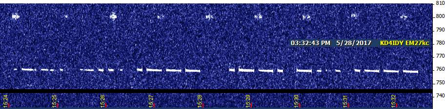
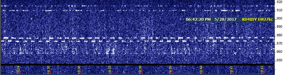
Monday Surprises: MTI2 and PCO
Apparently, MTI has made some significant changes. It was mildly interesting yesterday to find MTI almost exactly on its nominal 13557.540 frequency, but that could have been mere coincidence. When it showed up there again today, I figured something was up! Turns out, the new ID cycle is "MTI2" and it is sent once per minute, right at the top of the minute. Not only did I get aural copy of the new ID, but I even lucked out and saw it in old Argo's NDB mode (which is harder to do than copying by ear, because the level is so touchy).
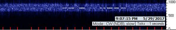
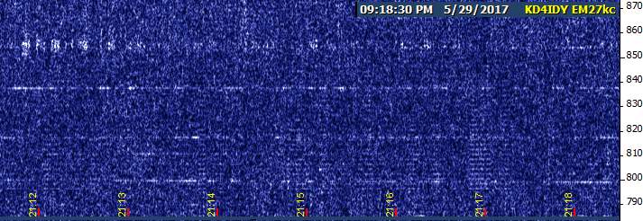
Next I spent some time watching for PLM, but there were no appearances tonight (saw and partially heard it in the afternoon). Then I went on up to 13563.5 as I usually do enroute to GNK. This time, a big surprise---PCO was audible for a couple of letters at a time! (Interestingly, "C" was the most common one to make it through. Codar tended to tear up the "O" worse than either P or C.) It didn't remain at audible level for very many cycles, but it was great to hear
John
---------------------------------------------------------------
![]() File Attachment 1: 29mayMTI2.jpg
File Attachment 1: 29mayMTI2.jpg
![]() File Attachment 2: 29mayPCO.jpg
File Attachment 2: 29mayPCO.jpg
Re: Monday Surprises: MTI2 and PCO
John,
Thanks for posting...I think your the very first to report hearing PCO...
73, power measurement or limitation on 13.56 Mhz
Bill in Pine Colorado
Posted by Stan AK0B on May 31, 2017 at 18:48:54.
I read the rules as -- The field strength of any emissions within the band 13.553-13.567 MHz shall not exceed 15,848 microvolts/meter at 30 meters
What would be an acceptable way to determine actually readings or to set output power to meet the requirement.
Thanks, Stan AK0B Re: power measurement or limitation on 13.56 Mhz
Posted by John Davis on May 31, 2017 at 21:04:35.
In reply to power measurement or limitation on 13.56 Mhz posted by Stan AK0B on May 31, 2017
Hi Stan,
The most reliable way of determining acceptable power, short of acquiring a calibrated loop and frequency selective RF voltmeter, is a variation on the same way it's done for FM and TV transmitters. Their coverage areas are defined by certain signal voltages appearing at certain distances from the transmitter, which both establish the areas in which they must be protected from interference and the areas in which they must not cause interference to other stations. But they don't actually measure those field intensities. Instead, extensive testing over the years has allowed mathematical models to be developed that predict signal levels over a variety of terrain with reasonable accuracy for a given effective radiated power emanating from an antenna having any specific height. That's the power level that is then assigned to that class of station by the FCC.
The licensed ERP is maintained by making measurements of the transmitter output down at ground level, fortunately. This can be done legitimately because the gain of the antenna establishes how much power is required at its input to achieve a given ERP, and antenna manufacturers determine this with great care. We can easily tell at ground level, then, how much power is going into the antenna if we know the loss of the transmission line for a given frequency and length of line. These figures are available also. Thus, an engineer who knows how much power is needed at the antenna terminals can work backward to determine the transmitter output power that is needed to achieve the authorized level, and calibrates the transmitter power meter to read 100% for that power.
At HiFER power levels, you're not going to find a Bird wattmeter that'll help much. :) An alternate approach is to establish a measurement point in the system where you know the impedance with some certainty (ie, ahead of whatever sort of tuner you use for the antenna, with it tuned for negligible VSWR), and then measure the RF voltage at that test point with either an RF millivoltmeter or a reasonably calibrated oscilloscope having the necessary bandwidth and a good RF probe that doesn't load the test point with excessive capacitance.
But what power should you shoot for at the antenna input terminals? That depends on the type of antenna, of course, and we've had some discussion of that before. One such post can be found here.
(That was in response to a question about how a 4.8 mW TPO figure was derived for a dipole in free space, incidentally. The actual value is probably closer to 4.6 mW, as seen in the post; and of course, horizontal dipoles are not the best antenna for a HiFER due to their directionality negating up to half of one's potential target audience. Same problem with loop antennas; plus the additional problem that their gain is harder to determine in real-world conditions than you might think.)
John
Re: power measurement or limitation on 13.56 Mhz
Posted by Stan AK0B on May 31, 2017 at 22:47:36.
In reply to Re: power measurement or limitation on 13.56 Mhz posted by John Davis on May 31, 2017
Thanks John, not much power. I have a oscilloscope and plan to put the xmtr at the base of a vertical. It will be interesting. I am building up a beacon using ICs but will need to use an attenuator and a good RF filter to make sure I am only measuring the fundamental frequency and not some harmonics.
I have ran 100 mill watts on 40 CW and that beacon was heard in 42 states. This will be a challenge.
Best Regards, and will see what happens in a couple of weeks still need the ICs to show up. Will post when its running.
Stan ak0b
potrzebie